
FW V06.XX/HAFM SW V08.02.00 HP StorageWorks SAN High Availability Planning Guide (AA-RS2DD-TE, July 2004)


Table Of Contents
- SAN HA Planning Guide
- Contents
- About this Guide
- Introduction to HP Fibre Channel Products
- Product Management
- Planning Considerations for Fibre Channel Topologies
- Fibre Channel Topologies
- Planning for Point-to-Point Connectivity
- Characteristics of Arbitrated Loop Operation
- Planning for Private Arbitrated Loop Connectivity
- Planning for Fabric-Attached Loop Connectivity
- Planning for Multi-Switch Fabric Support
- Fabric Topologies
- Planning a Fibre Channel Fabric Topology
- Fabric Topology Design Considerations
- FICON Cascading
- Physical Planning Considerations
- Port Connectivity and Fiber-Optic Cabling
- HAFM Appliance, LAN, and Remote Access Support
- Inband Management Access (Optional)
- Security Provisions
- Optional Features
- Configuration Planning Tasks
- Task 1: Prepare a Site Plan
- Task 2: Plan Fibre Channel Cable Routing
- Task 3: Consider Interoperability with Fabric Elements and End Devices
- Task 4: Plan Console Management Support
- Task 5: Plan Ethernet Access
- Task 6: Plan Network Addresses
- Task 7: Plan SNMP Support (Optional)
- Task 8: Plan E-Mail Notification (Optional)
- Task 9: Establish Product and HAFM Appliance Security Measures
- Task 10: Plan Phone Connections
- Task 11: Diagram the Planned Configuration
- Task 12: Assign Port Names and Nicknames
- Task 13: Complete the Planning Worksheet
- Task 14: Plan AC Power
- Task 15: Plan a Multi-Switch Fabric (Optional)
- Task 16: Plan Zone Sets for Multiple Products (Optional)
- Index
Planning Considerations for Fibre Channel Topologies
112 SAN High Availability Planning Guide
Port Numbering Versus Port Addressing
Consideration must be given to the implications of port numbering for the FCP
protocol versus logical port addressing for the FICON protocol. FCP
configuration attributes are implemented through zoning. Zones are configured
through the associated Element Manager application by authorizing or restricting
access to name server information associated with device N_Ports that attach to
director or switch F_Ports.
Zones are configured by:
■ The 8-byte (64-digit) WWN assigned to the host bus adapter (HBA) or Fibre
Channel interface installed in a device connected to the director or switch.
■ The domain identification (ID) and physical port number of the director or
edge switch port to which a device is attached.
FICON configuration attributes are implemented through logical port addressing.
This concept is consistent with the address-centric nature of FICON and allows
ports to be swapped for maintenance operations without regenerating a host
configuration.
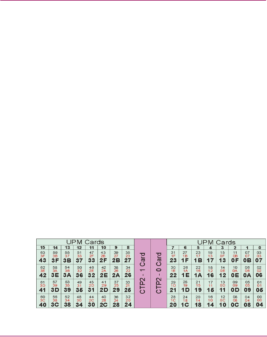
Logical port addresses are derived by converting the port number from numerical
to hexadecimal format and adding a hexadecimal 4 to the result. Figure 46
illustrates port numbering and logical port addressing for the Director 2/64. The
figure shows:
■ Universal port module (UPM) card numbers at the top (numerical 0 through
15).
■ Numerical physical port numbers in blue (00 through 63).
■ Hexadecimal physical port numbers in red (00 through 3F).
■ Logical port addresses in bold (hexadecimal 04 through 43).
Figure 46: Director 2/64 port numbers and logical port addresses