
HP StorageWorks EVA6400/8400 M6412A disk enclosure installation instructions
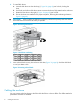
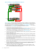

9. Power on controller A by pressing the power button on rear of the controller until the controller
responds (it may take up to 10 seconds for the controller to power on). Repeat this step for
controller B. Wait five minutes for the array to stabilize.
10. Verify that I/O modules A and B on the added disk enclosure have been assigned an index
number of the next higher enclosure number. For example, if the previous highest index number
was “3,” then the installed enclosure should display “4.”
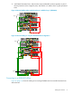
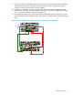
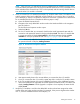
11. In HP P6000 Command View, verify that the newly installed disk enclosure appears as part of
the array hardware in the navigation pane, and that the I/O modules show a good operational
status.
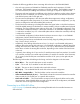
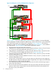
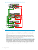
Figure 17 Revised cabling when one disk enclosure is added to loop 1 (EVA8400)
PS 2
MemoryCard
UID
Mfg
DP1-A DP2-A DP3-A MP 1 FP1 FP2 FP3 FP4 MP2 DP1-B DP2-B DP3-B
PS 1
PS 2
MemoryCard
UID
Mfg
DP1-A DP2-A DP3-A MP 1 FP1 FP2 FP3 FP4 MP2 DP1-B DP2-B DP3-B
PS 1
Controller “A”
Controller “B”
MP1 – MP2 –
Jumper Cables
DP1-A / DP2-A / DP3-A
DP1-B / DP2-B / DP3-B
DP1-B / DP2-B / DP3-B
Shelf-3 (S-3)
DP1-A / DP2-A / DP3-A
02
02
03
03
Shelf-4 (S-4)
P1 / P2P1 / P2
I/O-A I/O-B
Loop 1
01
01
04
04
P1 / P2P1 / P2
I/O-A I/O-B
Cabling the enclosure 13