
HP StorageWorks EVA6400/8400 M6412A disk enclosure installation instructions
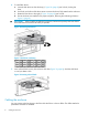
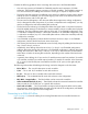
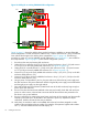
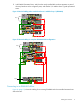
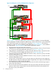
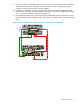
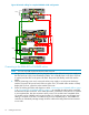

Figure 16 Cabling for an existing EVA8400 2C3D configuration
PS 2
MemoryCard
UID
Mfg
DP1-A DP2-A DP3-A MP 1 FP1 FP2 FP3 FP4 MP2 DP1-B DP2-B DP3-B
PS 1
PS 2
MemoryCard
UID
Mfg
DP1-A DP2-A DP3-A MP 1 FP1 FP2 F P3 FP4 MP2 DP 1-B DP2-B DP3-B
PS 1
Controller “A”
Controller “B”
P1 / P2P1 / P2
I/O-A I/O-B
MP1 – MP2 –
Jumper Cables
DP1-A / DP2-A / DP3-A
DP1-B / DP2-B / DP3-B
DP1-B / DP2-B / DP3-B
P1 / P2P1 / P2
I/O-A I/O-B
P1 / P2P1 / P2
I/O-A I/O-B
Shelf-3 (S-3)
Shelf-2 (S-2)
Shelf-1 (S-1)
DP1-A / DP2-A / DP3-A
01
01
02
02
05
05
06
06
09
09
10
10
03
03
04
04
07
07
08
08
11
11
12
12
Loop 2
Loop 3
Loop 1
Figure 17 (page 13) shows the cabling when one disk enclosure is added to an existing EVA8400
2C3D configuration. The disk enclosure is added to loop 1 above disk enclosure 3 (S-3). The dashed
lines indicate the changes to the cabling when compared to Figure 16 (page 12). The following
procedure is written so it can be adapted; specific references to Figure 17 (page 13) are included to
aid comprehension. Figure 18 (page 14) shows the full configuration (2C4D).
1. Power down the array and existing disk enclosures.
2. Unplug DP1-A on controller A from P1 (I/O-A) on the disk enclosure in loop 1 (S-3) and connect
it to P1 (I/O-A) on the newly added disk enclosure (S-4 in Figure 17 (page 13)).
3. Unplug DP1-B on controller B from P1 (I/O-B) on the disk enclosure in loop 1 (S-3) and connect
it to P1 (I/O-B) on the newly added disk enclosure (S-4 in Figure 18 (page 14)).
4. Connect P2 (I/O-A) on the newly added disk enclosure in loop 1 (S-4) to P1 (I/O-A) on the disk
enclosure directly below it (S-3).
5. Connect P2 (I/O-B) on the newly added disk enclosure in loop 1 (S-4) to P1 (I/O-B) on the disk
enclosure directly below it (S-3).
6. Using a power cord provided in your kit, plug one end into a disk enclosure power supply and
the other end into a rack power distribution module. Plug the left power supply into the left module
and the right power supply into the right module.
7. Press and hold the power push-button (located at the rear of the disk enclosure) long enough to
power up the disk enclosure.
8. Power on the other disk enclosures attached to the array and visually check that each enclosure
powers on without errors. Wait at least one minute after all the enclosures are powered on for
the drives to spin up and stabilize.
12 Cabling the enclosure