
HP StorageWorks EVA6400/8400 M6412A disk enclosure installation instructions
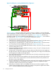
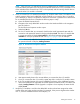

11. In HP P6000 Command View, verify that the newly installed disk enclosure appears as part of
the array hardware in the navigation pane, and that the I/O modules show a good operational
status.
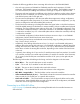
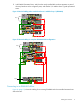
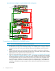
Figure 14 Revised cabling when one disk enclosure is added to loop 1 (EVA6400)
PS 2
MemoryCard
UID
Mfg
DP1-A DP2-A MP1 FP1 FP2 FP3 FP4 MP2 DP1-B DP2-B
PS 1
PS 2
MemoryCard
UID
Mfg
DP1-A DP2-A MP1 FP1 FP2 FP3 FP4 MP2 DP1-B DP2-B
PS 1
DP1-A / DP2-A
DP1-A / DP2-A
DP1-B / DP2-B
Controller “A”
Controller “B”
Shelf-2 (S-2)
Shelf-2 (S-2)
MP1 – MP2 –
Jumper Cables
DP1-B / DP2-B
03
03
P1 / P2P1 / P2
I/O-A I/O-B
P1 / P2P1 / P2
I/O-A I/O-B
Shelf-3 (S-3)
01
01
04
04
02
Loop 1
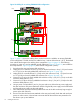
Figure 15 Revised cabling for complete EVA6400 2C3D configuration
PS 2
MemoryCard
UID
Mfg
DP1-A DP2-A MP1 FP1 FP2 FP3 FP4 MP2 DP1-B DP2-B
PS 1
PS 2
MemoryCard
UID
Mfg
DP1-A DP2-A MP1 FP1 FP2 FP3 FP4 MP2 DP1-B DP2-B
PS 1
P1 / P2P1 / P2
I/O-A I/O-B
DP1-A / DP2-A
DP1-A / DP2-A
DP1-B / DP2-B
Controller “A”
Controller “B”
Shelf-2 (S-2)
Shelf-1 (S-1)
Shelf-2 (S-2)
MP1 – MP2 –
Jumper Cables
DP1-B / DP2-B
05
05
02
02
06
06
03
03
07
08
08
07
P1 / P2P1 / P2
I/O-A I/O-B
P1 / P2P1 / P2
I/O-A I/O-B
Shelf-3 (S-3)
01
01
04
04
Loop 1
Loop 2
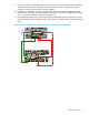
Connecting to an EVA8400 offline
Figure 16 (page 12) shows the cabling for an existing EVA8400 with the controllers between three
disk enclosures.
Cabling the enclosure 11