
HP StorageWorks controller enclosure replacement instructions (514016-001, March 2009)

HP
StorageWorks
HSV450
UID
ENTERESC
gl0127
1
2
3
4
5
6
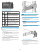
Figure 1 Controller status LEDs
Table 1 Controller s tatus LEDs
Item LED
Indication
1
Solid amber indicates a boot failure.
2
Controller health OK. Flashing green
during boot. Solid green LED after b oot.
3
Link to the other array controller. Solid
green indicates a connection. Amber
indicates the controllers are not connected.
4
Disk drive status. Solid green when
devices and loops are present. Amber
indicates a drive problem.
5
Battery status. Solid green indicates all
fan units are normal. Amber indicates one
or more battery units have failed.
6
Blue LED used to identify a specific
controller enclosure.
Removing
components from a controller
enclosure
1. Halt I/O to the controller enclosure being replaced with HP
Command View EVA:
a. In the navigation pane, select the array. The Initializ ed Storage
System Properties window opens.
b. Click the Shut down tab. The Shutdown Options window
opens.
c. In the Controller Shutdown section, select the controller to
power down, and click Power down.
2. Disconnect the Fibre Channel, serial (RJ45), and power cables
from the rear of the controller enclosure. Ensure they are marked
to facilitate reconnecting later.
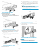
3. Remove the front bezel by grasping the bezel at each end and
pulling it off the enclosure (Figure 2).
Figure 2 Removing the front bezel
NOTE:
To provide clarity, the controller enclosure is shown out of the
cabinet in subsequent figures showing component removal.
4. Remove the
operator control panel (OCP).
a. Squeeze th
eOCPlatchtabs(1,Figure 3) and swing the panel
out until fully open (2).
CAUTION:
Handle the OCP by its metal frame only. This ensures
that the electronic components a re not damaged by static
discharge.
b. Grasp the OCP by its metal frame and pull it out of the
enclosure (3).
Figu
re 3 Removing the OCP
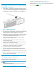
5. Rem
ove the ca che batteries. Some controller enclosure models
hav
eacachebatterylocatedbehindtheremovedOCP.
a. Mov
e the batter y mounting latch (1, Figure 4)totherightand
gr
asp the pull handle.
b. Po
sition one hand under the battery, and pull the battery out
of
the enclosure (2).
Page 2