
HP Enterprise Virtual Array 6400/8400 Expansion Rack Reference Guide (5697-1818, March 2012)

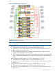
General EVA8400 expansion cabling guidelines
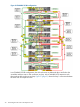
To adapt the cabling used in Figure 25 (page 28) to different configurations, follow these cabling
guidelines:
• Controller A
DP1-A on controller A connects to P1 (I/O-A) on the top disk enclosure in the first loop
(expansion rack).
◦
◦ DP2-A on controller A connects to P1 (I/O-A) on the top disk enclosure in the second loop
(expansion rack).
◦ DP3-A on controller A connects to P1 (I/O-A) on the top disk enclosure in the third loop
(expansion rack).
◦ DP1-B on controller A connects to P2 (I/O-B) on the bottom disk enclosure in the first loop
(main rack).
◦ DP2-B on controller A connects to P2 (I/O-B) on the bottom disk enclosure in the second
loop (main rack).
◦ DP3-B on controller A connects to P2 (I/O-B) on the bottom disk enclosure in the third
loop (main rack).
• Controller B
DP1-A on controller B connects to P2 (I/O-A) on the bottom disk enclosure in the first loop
(main rack).
◦
◦ DP2-A on controller B connects to P2 (I/O-A) on the bottom disk enclosure in the second
loop (main rack).
◦ DP3-A on controller B connects to P2 (I/O-A) on the bottom disk enclosure in the third
loop (main rack).
◦ DP1-B on controller B connects to P1 (I/O-B) on the top disk enclosure in the first loop
(expansion rack).
◦ DP2-B on controller B connects to P1 (I/O-B) on the top disk enclosure in the second loop
(expansion rack).
◦ DP3-B on controller B connects to P1 (I/O-B) on the top disk enclosure in the third loop
(expansion rack).
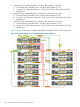
• Disk enclosures
P1 (I/O-A) on the top disk enclosure in the first loop (main rack) goes to P2 (I/O-A) on
the bottom disk enclosure in the first loop (expansion rack).
◦
◦ P1 (I/O-B) on the top disk enclosure in the first loop (main rack) goes to P2 (I/O-B) on
the bottom disk enclosure in the first loop (expansion rack).
◦ P1 (I/O-A) on the top disk enclosure in the second loop (main rack) goes to P2 (I/O-A)
on the bottom disk enclosure in the second loop (expansion rack).
◦ P1 (I/O-B) on the top disk enclosure in the second loop (main rack) goes to P2 (I/O-B)
on the bottom disk enclosure in the second loop (expansion rack).
◦ P1 (I/O-A) on the top disk enclosure in the third loop (main rack) goes to P2 (I/O-A) on
the bottom disk enclosure in the third loop (expansion rack).
◦ P1 (I/O-B) on the top disk enclosure in the third loop (main rack) goes to P2 (I/O-B) on
the bottom disk enclosure in the third loop (expansion rack).
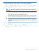
Connecting an EVA8400 2C18D rack to a 0C9D expansion rack
For reference, Figure 26 (page 30) shows a fully cabled EVA8400 2C18D configuration.
Online expansion 29