
HP Enterprise Virtual Array 6400/8400 Expansion Rack Reference Guide (5697-1818, March 2012)
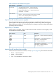


4. Unplug DP1-B on controller B from P1 (I/O-B) on disk enclosure 1 (S-1) and:
a. Connect DP1-B on controller B to P1 (I/O-B) on disk enclosure 7 (S-7).
b. Connect P1 (I/O-B) on disk enclosure 1 (S-1) to P2 (I/O-B) on disk enclosure 9 (S-9).
c. Repeat Step 2.
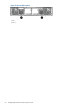
5. Unplug DP2-B on controller B from P1 (I/O-B) on disk enclosure 4 (S-4) and:
a. Connect DP2-B on controller B to P1 (I/O-B) on disk enclosure 10 (S-10).
b. Connect P1 (I/O-B) on disk enclosure 4 (S-4) to P2 (I/O-B) on disk enclosure 12 (S-12).
c. Repeat Step 2.
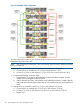
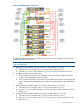
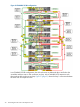
Figure 23 (page 25) shows the completed cabling for an EVA6400 2C6D to 0C6D expansion.
Figure 23 Complete cabling for an EVA6400 2C6D to 0C6D expansion
General EVA6400 expansion cabling guidelines
To adapt the cabling used in Figure 23 (page 25) to different configurations, follow these cabling
guidelines:
• Controller A
DP1-A on controller A connects to P1 (I/O-A) on the top disk enclosure in the first loop
(expansion rack).
◦
◦ DP2-A on controller A connects to P1 (I/O-A) on the top disk enclosure in the second loop
(expansion rack).
Online expansion 25