
HP Enterprise Virtual Array 6400/8400 Expansion Rack Reference Guide (5697-1818, March 2012)
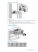

7. Power on the rack distribution units.
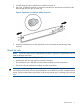
8. Press and hold power push button (located at the rear of the disk enclosure) long enough to
power up the disk enclosure.
9. Repeat Step 8 for each disk enclosure in the expansion rack.
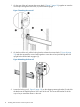
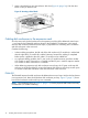
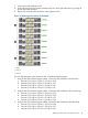
Figure 19 0C9D expansion rack for the EVA8400
1. Loop 1
2. Loop 2
3. Loop 3
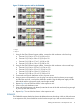
For nine disk enclosures in the expansion rack, complete the following steps:
1. Using 0.41m Fiber Channel copper cables, connect the disk enclosures in the first loop:
a. Connect P2 (I/O-A) on S-19 to P1 (I/O-A) on S-20.
b. Connect P2 (I/O-A) on S-20 to P1 (I/O-B) on S-21.
c. Connect P2 (I/O-B) on S-19 to P1 (I/O-B) on S-20.
d. Connect P2 (I/O-B) on S-20 to P1 (I/O-B) on S-21.
2. Using 0.41m Fiber Channel copper cables, connect the disk enclosures in the second loop:
a. Connect P2 (I/O-A) on S-22 to P1 (I/O-A) on S-23.
b. Connect P2 (I/O-A) on S-23 to P1 (I/O-A) on S-24.
c. Connect P2 (I/O-B) on S-22 to P1 (I/O-B) on S-23.
d. Connect P2 (I/O-B) on S-23 to P1 (I/O-B) on S-24.
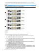
3. Using 0.41m Fiber Channel copper cables, connect the disk enclosures in the third loop:
a. Connect P2 (I/O-A) on S-25 to P1 (I/O-A) on S-26.
b. Connect P2 (I/O-A) on S-26 to P1 (I/O-A) on S-27.
c. Connect P2 (I/O-B) on S-25 to P1 (I/O-B) on S-26.
Cabling disk enclosures in the expansion rack 19