
HP Enterprise Virtual Array 6400/8400 Expansion Rack Reference Guide (5697-1818, March 2012)

an expansion rack, there should be three disk enclosures per loop. Figure 18 (page 18) and
Figure 19 (page 19) show how the disk enclosures within each loop are connected in both of these
scenarios.
NOTE: The numbering shown in Figure 18 (page 18) and Figure 19 (page 19) is for the physical
shelf location and may not reflect the I/O module numbering.
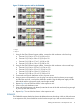
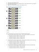
Figure 18 0C6D expansion rack for the EVA8400
1. Loop 1
2. Loop 2
3. Loop 3
For six disk enclosures in the expansion rack, complete the following steps:
1. Using 0.41m Fiber Channel copper cables, connect the disk enclosures in the first loop:
a. Connect P2 (I/O-A) on S-7 to P1 (I/O-A) on S-8.
b. Connect P2 (I/O-B) on S-7 to P1 (I/O-B) on S-8.
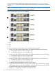
2. Using 0.41m Fiber Channel copper cables, connect the disk enclosures in the second loop:
a. Connect P2 (I/O-A) on S-9 to P1 (I/O-A) on S-10.
b. Connect P2 (I/O-B) on S-9 to P1 (I/O-B) on S-10.
3. Using 0.41m Fiber Channel copper cables, connect the disk enclosures in the third loop:
a. Connect P2 (I/O-A) on S-11 to P1 (I/O-A) on S-12.
b. Connect P2 (I/O-B) on S-11 to P1 (I/O-B) on S-12.
4. Connect the rack power distribution units to a power source.
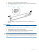
5. Using a power cord provided in your kit, plug one end into a disk enclosure power supply
and the other end into a rack power distribution module. Plug the left power supply into the
left module and the right power supply into the right module.
6. Repeat Step 5 for each disk enclosure in the expansion rack.
18 Installing disk enclosures into the expansion rack