
HP Enterprise Virtual Array 6400/8400 Expansion Rack Reference Guide (5697-1818, March 2012)
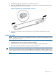
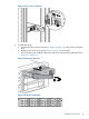
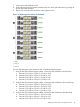

7. Insert a drive blank into any slot without a disk drive (Figure 16 (page 16)). Push the drive
blank in until you detect a click.
Figure 16 Inserting a drive blank
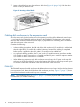
Cabling disk enclosures in the expansion rack
As in the main rack, the disk enclosures in the expansion rack should be balanced across loops
— two loops for the EVA6400 and three loops for the EVA8400. The diagrams in this section
show the disk enclosures balanced across loops, in preparation for connecting to the controllers
and disk enclosures in the main rack.
Consider the following:
• In these cabling procedures, the left side of the disk enclosure (I/O module A) is cabled and
then the right side (I/O module B) is cabled. However, because this cabling is completed
before power is applied to the rack, either I/O module can be cabled first.
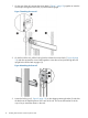
• As a general cabling guideline, the P1 port on the I/O module receives input from another
I/O module or return connection to a controller and the P2 port is used for output to another
I/O module or return connection to a controller.
• When balancing expansion rack disk enclosures across loops, the P1 ports on the top disk
enclosure in the loop and the P2 ports on the bottom disk enclosure in the loop remain open
to connect to either the controllers or the disk enclosures in the main rack.
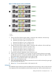
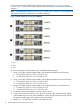
EVA6400
The EVA6400 requires that disk enclosures be balanced across two loops. With six disk enclosures
in an expansion rack, there should be three disk enclosures per loop. Figure 17 (page 17) shows
how the disk enclosures within each loop are connected.
NOTE: The numbering shown in Figure 17 (page 17) is for the physical shelf location and may
not reflect the I/O module numbering.
16 Installing disk enclosures into the expansion rack