HP Insight Environmental Configurator User Guide Part Number 571192-003 November 2010 (Third Edition)
© Copyright 2009, 2010 Hewlett-Packard Development Company, L.P. The information contained herein is subject to change without notice. The only warranties for HP products and services are set forth in the express warranty statements accompanying such products and services. Nothing herein should be construed as constituting an additional warranty. HP shall not be liable for technical or editorial errors or omissions contained herein. Confidential computer software.
Contents Overview ..................................................................................................................................... 5 About HP Insight Environmental Configurator .................................................................................................. 5 System requirements ..................................................................................................................................... 5 Hardware requirements ...................................
Exporting the configuration file .................................................................................................................... 96 Clearing object IDs..................................................................................................................................... 97 Removing an exported file........................................................................................................................... 98 Maintaining an existing project ..................
Overview About HP Insight Environmental Configurator HP Insight Environmental Configurator is a stand-alone software application that enables you to create or edit the relative layout of sensor objects on a data center floor plan map. The layout is exported into the HP Insight Environmental Application Server as the background image for the database. The image visually displays the configuration information for all sensor objects within the data center.
• General • Environmental • Power and Energy • Calculations Callout Interface item Description 1 Tool bar Enables you to select the operations that are performed on objects that have been placed on the map. 2 Configuration tree Displays categories of objects and sensors that can be placed on the map. 3 Object window Enables you to select objects from this window to place on the map. 4 Map window Displays the map and graphic representation of objects.
• Advanced—(Default) Permission to export new or updated configuration data to the Edge server. • Expert—Permission to export new or update configuration data to the Edge server, change user access codes, clear object IDs, export configuration files to XML, or remove existing configuration data from the Edge server. Some menus and menu options are only available if you are using Advanced or Expert user credentials. To change a user level: 1. From the Setup menu, select Change User Level.
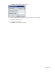
The Change Access Code window appears. 2. Select the user level from the menu for the access code you want to change. 3. Enter the current access code. 4. Enter the new access code. 5. Select OK to save the new access code.
Creating a project Starting a new configuration project The Configurator software associates a configuration project to a specific monitored data center. Therefore, if you have more than one data center monitored on the same server, then each data center must have its own configuration project. You must configure each project and individually export each project to the server before the installation is complete and the sensors report data to the Observer software.
1. Select File> New project. A window appears with your original background image and the transparent background image. 2. Select the transparent floor plan image file, and select Open. The image appears in the center work window of the HP Insight Environmental Configurator. HP Insight Environmental Configurator adjusts the size of the background image to 2879 pixels.
1. Select Setup>Set background scale. The following message appears. NOTE: The standard floor tile is approximately 0.6 m (2 ft) and can be used for a reference point when setting the background scale. 2. Select a location on the background to establish an anchor, and then select another point approximately 0.6 m (2 ft) away from the anchor point. 3. Repeat steps 1-2 as necessary. To manually set the scale using metric units: 1. On the Groupings tab, select the appropriate data center.
2. In the properties for the data center, set the scale to the desired value. General configuration options Before you can export a project to the HP Insight Environmental Application Server, you must set the output directory for HP Insight Environmental Imaging Server and IP address of the Application Server. To set the options: NOTE: The default output path for Imaging Server background images is C:\Program Files\HP\HP Insight Environmental Software\HP Insight Environmental Configurator. 1.
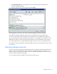
The General Configuration Options window appears. 2. Enter the Environmental Application Server Host IP address. If the HP Insight Environmental Imaging Server is installed on the same server as the Application Server, the IP address is 127.0.0.1 or localhost. If they are installed on different servers, you must specify the actual IP address for the Environmental Application Server. 3. Select the unit measurement type. 4. Select OK to save and close, or select Cancel.
one gateway, but it can have more gateways for redundancy or to speed the data collection process. HP recommends installing at least two gateways for each WSN data source. To create a WSN data source: 1. Add a WSN data source, using one of the following options: o Select Data Sources>Add WSN Network. o From the side of the Data Sources tab, select the Add WSN Network icon. The Add New Network window appears. 2. Enter the name of the new network, and select OK. 3. Configure the WSN network. a.
b. Select the network you want to configure. c. Specify the PAN ID for the network. The PAN ID is the unique identifier of the WSN network, composed of a four character hexadecimal number, such as AAAA. Each WSN network consists of one or more gateways and up to 400 wireless base stations. NOTE: In the value string, be careful to follow these recommendations: • Start each IP address with TCP:. • Separate each IP address with a comma. • Do not leave any empty spaces. d.
Edge server. Each Wired data source must have at least one gateway, but it can have more gateways for redundancy or to speed the data collection process. HP recommends installing at least two gateways for each Wired data source. The Wired data source supports all legacy data source configurations. It is only accessible if the HP Wired Plug-In has been installed and configured within Device Manager. For more information, see the HP Insight Environmental Software Installation Guide.
3. Configure the Wired network. a. On the Data Sources tab, select Wired to expand and display all of the Wired networks. b. Select the network you want to configure. c. Specify the In Broadcast IP address for the network. d. Specify the Out Broadcast IP address for the network. Creating a Modbus/RTU data source A Modbus/RTU data source is an RS-485 based network that uses the Modbus/RTU serial protocol to gather data from the equipment in the Modbus network.
o Select Data Sources>Modbus>Add Modbus/RTU Network. o From the side of the Data Sources tab, select the Add Modbus/RTU Network icon. The Add Modbus/RTU Network window appears. 2. Enter the name of the new network, and select OK. 3. Configure the Modbus/RTU network. a. On the Data Sources tab, select Modbus to expand and display all the Modbus networks.
b. Select the network you want to configure. c. Specify the response timeout in seconds. The response timeout is the maximum amount of time the Application server expects the Modbus device to respond to a request. The default is 3000. d.
To create a Modbus/TCP data source: 1. Add a Modbus/TCP data source using one of the following options: o Select Data Sources>Modbus>Add Modbus/TCP Network. o From the side of the Data Sources tab, select the Add Modbus/TCP Network icon. The Add Modbus/TCP Network window appears. 2. Configure the Modbus/TCP network. a. On the Data Sources tab, select Modbus to expand and display the Modbus networks.
b. Select the network you want to configure. c. Specify the response timeout in seconds. The response timeout is the maximum amount of time the Application server expects the Modbus device to respond to a request. The default value is 3000. NOTE: In the value string, be careful to follow these recommendations: • Start each IP address with TCP:. • Separate each IP address with a comma. • Do not leave any empty spaces. d. Specify the gateway IP addresses for the network.
NOTE: An SNMP data source is required for each SNMP device. To create an SNMP data source: 1. Add an SNMP data source using one of the following options: o Select Data Sources>SNMP> Add SNMP Agent. o From the side of the Data Sources tab, select one of the Add SNMP agent icons. The Add SNMP Agent window appears. 2. Enter the name of the new SNMP data source, and select OK. 3. Configure the SNMP data source device. a.
b. Select the SNMP device. c. 4. Configure the properties available. Create a calculation group ("Creating calculation groups" on page 25) for SNMP objects. SNMP versions When creating your SNMP data source, select the SNMP version that correlates to the type of SNMP device you have in your data center. For example, if you have a SNMPv2 device in your data center, then create a SNMPv2 data source.
Creating zones A zone is a logical grouping of wireless sensor objects within a WSN. For example, if your data center has separate rooms, then each room might be a zone. Alternatively, a large data center room might include multiple zones. The background image automatically divides the map into rectangle zones. A project must have at least one zone. Because the Imaging thermal map is configured at a zone level, selecting the zone scope affects the imaging results from high to low granularity.
3. On the Devices tab, double-click the zone you want to adjust. 4. Set the zone properties. o Border Pixels—The amount of the image included in the rectangle used for the floor plan in the HP Insight Environmental Observer. The Configurator trims the rectangle to include only objects within the zone. The default value is 10 pixels. The Configurator adds an additional 10 pixels in each direction beyond the rectangle that includes all objects in that zone.
cooling power, IT power, building and IT power loss, and lighting and general electric power. For more information, see Adding a PUE reporter (on page 57). To create a calculation group: 1. Add a calculation group using one of the following methods: o Select Groupings> Add Calculation Group. o From the side of the Groupings tab, select the Add Calculation Group icon. The Add New Calculation Group window appears. 2. Enter the name of the calculation group, and select OK.
3. On the Devices tab, double-click the calculation group you want to adjust. 4. Set the calculation group properties. o Name—The name of the calculation group that appears in the HP Insight Environmental Observer Navigation panel. o Description—Additional descriptive information about the calculation group that appears when you scroll over the calculation group in the HP Insight Environmental Observer Navigation panel. o Configuration—The configuration of the group (calculation group).
• • Wireless—A physical device that communicates its data over a wireless network: o Gateway o Leak detector o Door sensor o Equipment status sensor Virtual—A symbolic device that is used for aggregating data from multiple PDU devices: PDU General objects are added to a zone ("Creating zones" on page 24). Adding a gateway object Gateways are the control base stations in a WSN, similar to a wireless access point. To add a gateway object to your floor plan: 1.
3. On the floor plan, select the location where the gateway is installed. A graphic representing your gateway object is added to your floor plan. 4. Select the new gateway object to configure the properties for the gateway. o Name—If you have multiple gateways, then you must change the name of each gateway to be unique. HP recommends that you use gateway names that help identify the object on the floor plan.
2. Select the Leak Detector icon. 3. On the floor plan, select the location where the leak detector is installed. A graphic representing your leak detector object is added to your floor plan. 4. Select the new leak detector object to configure the properties for the sensor. 5. Repeat for all leak detector sensor locations. Adding a door sensor object A door sensor is a magnetic switch that monitors whether or not a rack door is open or closed.
2. Select the Door Sensor icon. 3. On the floor plan, select the location where the door sensor is installed. A graphic representing your door sensor object is added to your floor plan. 4. Select the new door sensor object to configure the properties for the sensor. 5. Repeat for all door sensor locations. Adding an equipment status sensor object An equipment status sensor consists of a base station and one CT collar, which determines whether the equipment is receiving power currents.
2. Select the Equipment Status icon. 3. On the floor plan, select the location where the equipment status sensor is installed. A graphic representing your equipment status sensor object is added to your floor plan. 4. Select the new equipment status object to configure the properties for the sensor. 5. Repeat for all equipment status sensor locations.
2. Select the Modbus Gateway icon. 3. On the floor plan, select the location where you want to place the virtual Modbus gateway object. A graphic representing your Modbus gateway is added to your floor plan. 4. Select the new virtual Modbus gateway to configure the properties. 5. Repeat for all virtual Modbus gateway locations. Adding a virtual PDU object A PDU sensor monitors and reports the amount of power available on each circuit of a PDU.
2. Select the PDU icon. 3. On the floor plan, select the location where you want to place the virtual PDU object. A graphic representing your PDU object is added to your floor plan. 4. Select the new virtual PDU object to configure the properties. 5. Associate one or more PDU devices to the virtual PDU object. a. Right-click a PDU device, and then select Associate. b. Select the PDU sensor you want to associate the PDU device to. The Select Association Type window appears.
c. Select the PDU panel from the left column to the virtual PDU object panel number in the right column. d. Select OK to save and close, or select Cancel to close without saving. On the floor plan, an arrow appears between the associated PDU objects, in the direction specified. 6. Repeat for all virtual PDU object locations. Adding a Modbus integrator A Modbus integrator is used to configure any non-ION power meter using a Modbus data source.
3. Select the modbus_integrator.dcl library, and then select Open. If a Modbus integrator component library is already loaded to the Configurator, the Confirm Overload Component Library window appears. After the Modbus integrator component library is uploaded to Configurator, the Modbus integrator icon can be added to your floor plan. 4. Select Configurations>General>Wired.
5. Select either the Modbus Integrator or the Modbus Integrator 32 icon. 6. On the floor plan, select the location where your non-ION power meter is installed. A new graphic representing the Modbus integrator is added to your floor plan.
7. Select the new Modbus integrator object to configure the properties for the non-ION power meter. a. Name the Modbus integrator according to the type of non-ION power meter it is supporting. b. Verify that the Data Type and Scaling Factor properties are configured according to the device capabilities. c. 8. Adjust the LSW ModBus Register and MSW ModBus Register properties to match your desired wording of a 32-bit register, by swapping data point values, if necessary.
Adding a wireless rack object Rack objects represent the sensor arrays installed on the rack to measure the temperature on the intake and exhaust sides of the rack. The following rack object types are available: • Standard Rack—The standard rack is equipped with sensors on the intake and exhaust sides of the rack. • Cold Only Rack—The rack has sensors only on the intake side of the rack.
6. Rotate the rack ("Rotating the rack orientation" on page 85), if necessary. 7. Repeat for all wireless rack sensor locations. Adding a CRAH/CRAC object There are several CRAH/CRAC sensor configurations: • CRAH Temp—A single CRAH base station with two external sensors that measure the temperature of the CRAH supply and return air.
3. On the floor plan, select the location where your CRAH sensors are installed. A graphic representing your CRAH/CRAC sensor object is added to your floor plan. 4. Select the new CRAH/CRAC object to configure the properties for the object. 5. Repeat for all CRAH/CRAC locations. Adding a pressure sensor object A pressure sensor object measures the difference in pressure between two areas.
To add an outdoor sensor object: 1. Select Configurations>Environmentals>Wireless>Other. 2. Select the Outdoor Temp/Humidity icon. 3. On the floor plan, select the location where the outdoor sensor is installed. A graphic representing your outdoor sensor object is added to your floor plan. 4. Select the new outdoor sensor object to configure the properties. 5. Repeat for all outdoor sensor objects.
The wired rack supports all legacy rack configurations. It is only accessible when the HP Wired Plug-In has been installed and configured within Device Manager. For more information, see the HP Insight Environmental Software Installation Guide. To add a wired rack object to your floor plan: 1. Select Configurations>Environmentals>Wired>Racks. 2. Select either the Wired Standard Rack or the Wired Cold Only Rack icon. 3. On the floor plan, select the rack where the sensors are installed.
1. Select Configurations>Environmentals>Containment. 2. Select the Contained Rectangle icon. 3. On the floor plan, select the location where you want to place the contained rectangle object. A graphic representing your contained rectangle is added to your floor plan. 4. Select the new contained rectangle to configure the properties.
5. Manually adjust the length and width properties of the contained rectangle to match the physical dimensions of the containment area. 6. Repeat for all contained rectangle locations. Adding a power and energy object There are two kinds of power and energy objects: • Wireless—A physical device that communicates its data over a wireless network. • Wired—A physical device that is hard-wired (Modbus/TCP) to communicate directly to a network.
2. Select the Energy icon. 3. On the floor plan, select the location where the energy sensor is installed. A graphic representing your energy object is added to your floor plan. 4. Double-click the new energy object to configure the properties for the energy sensor. 5. Repeat for all energy sensor locations. Adding a 3-collar CT object A 3-collar CT sensor collects the amount of current, or total power, used by a three phase power device. To add a 3-collar CR sensor object to your floor plan: 1.
2. Select the 3-Collar CT icon. 3. On the floor plan, select the location where the 3-collar CT sensor is installed. A graphic representing your sensor is added to your floor plan. 4. Select the 3-collar CT object to configure the properties. 5. Repeat for all 3-collar CT sensor locations.
2. Select the Single Flow Energy Meter icon. 3. On the floor plan, select the location where the single-flow energy meter is installed. A graphic representing your energy meter is added to your floor plan. 4. Select the new sensor object to configure the properties for the single-flow energy meter. 5. Repeat for all single-flow energy meter locations.
2. Select the Dual Flow Energy Meter icon. 3. On the floor plan, select the location where the dual-flow energy meter is installed. A graphic representing your energy meter is added to your floor plan. 4. Select the new sensor object to configure the properties for the dual-flow energy meter. 5. Repeat for all dual-flow energy meter locations. Adding a BCMS Panel object A BCMS panel sensor monitors the current of each circuit of a PDU. The measurements are then used to calculate PUE data.
NOTE: You must have a Modbus/TCP Network data source in order to add this object to your floor plan. For more information, see Creating a Modbus/TCP data source (on page 19). To add a BCMS panel sensor object to your floor plan: 1. Select the Modbus/TCP data source and specific Grouping where you want to add the BCMS panel object. 2. Select Configurations>Power & Energy>Wired>BCMS. 3. Select the Square D BCMS Panel icon. 4. On the floor plan, select the location where the BCMS sensor is installed.
5. On the Groupings tab, select the new BCMS object to configure the properties for the BCMS sensor. 6. Repeat for all BCMS sensor locations. Adding an ION power meter object An ION power meter, also referred to as a kWh energy base station, measures the power consumption of a specific device or location. Two ION objects are available in the Configurator: • ION Wye—Used when the measured power line uses a Wye connection. • ION Delta—Used when the measured power line uses a Delta connection.
1. Select the Modbus/TCP data source and specific Grouping where you want to add the ION sensor object. 2. Select Configurations>Power & Energy>Wired>Power. 3. Select either the ION Wye or ION Delta icon.
4. On the floor plan, select the location where the ION power meter is installed. A graphic representing your ION object is added to your floor plan. 5. Select the new ION object to configure the properties. NOTE: The ION meter Modbus ID must match the physical connection of the ION meter. For example, if multiple ION meters are serially connected using RS485 cables, on the same RS485 channel or bus, then each ION meter must have a unique Modbus ID (1, 2, 3, etc.
Configuring other power meter devices You can add and configure other (non-ION6200) power meters that support Modbus protocol, such as a multi-function meter, within the HP Insight Environmental Configurator software by uploading the modbus_integrator.dcl external component library. The non-ION6200 power meter does not appear on the Power Meters tab in the Observer software, but its readings can be used to calculate PUE data. 1. Select File>Load Component Library to load an external component library.
b. Select the Modbus Integrator icon. c. 5. On the floor plan, select the location where the power meter is installed. A graphic representing your power meter object is added to your floor plan. From the Active Data Source drop down menu, select Modbus.
6. Select the new Modbus Integrator object to configure the properties for the power meter. a. Edit the Modbus Name to reflect the power meter you are configuring. b. Edit the Modbus ID and Register so that the power variable can be extracted for PUE calculation. The Register should be equal to the total active power (kW) for the power meter. For more information, see the documentation from the power meter manufacturer.
Adding a calculation object A calculation object is a symbolic object that is used to calculate metric power consumption data. After you add and configure the calculation objects, the PUE chart appears on the HP Insight Environmental Observer interface.
2. Select the PUE Reporter icon. 3. On the floor plan, select a location for the object. A graphic representing the PUE reporter is added to your floor plan. 4. Add additional PUE calculation objects to your floor plan and associate them to the PUE reporter or calculation group. 5. Export the project ("Exporting the configuration file" on page 96) to begin collecting data for PUE calculations.
Icon Calculation Description Average operation Calculates the average of associated power sources. Sum operation Calculates the sum of associated power sources. User input Insert a fixed value or known value, such as the amount of power consumed, as displayed on a utility statement. Rated power loss (output) Simulates equipment with a rated power loss (such as a transformer or UPS) where the only known value is the output or secondary power.
Icon Calculation Description Absolute value Computes the absolute value of an input value. Square Squares an input value. Square root Computes the square root of an input value. Log e Computes the natural logarithm (base e) of an input value. Log 10 Computes the common logarithm (base 10) of an input value.
1. Select Configurations>Calculations>Power Calculations. 2. Select the power calculation you want to compute. 3. On the floor plan, select the location for your calculation object. A graphic representing your calculation object is added to your floor plan.
4. Select the Association icon, then select the object you want to calculate. 5. Select the new calculation object you just added to associate that object to the calculation object. For example, if you add a Log 10 calculation object to your floor plan to calculate the common logarithm of a specific object, you would select the association icon, then select the object you want to calculate, and lastly select the new Log 10 calculation object.
1. In the Property Value table, select [Table] from the Efficiency Table property. The Efficiency window appears. 2. Specify the efficiency values, as described in the device specification documentation. Adding equipment status calculations NOTE: PUE objects are symbolic and do not represent a physical device within the data center.
1. Select Configurations>Calculations>Equipment Status Calculations. 2. Select the equipment status calculation you want to compute: o Fixed value switch—A status input of a fixed value, either on or off, as detected by a Current Sensor base station. When the sensor detects power (the equipment is on), the output is the Fixed Value amount of power. When the sensor does not detect any power (equipment is off), the output is the Default Value (0.0). You can configure both values in the property table.
o Input value switch—A status input for a power meter, which detects whether the equipment is on or off. When the equipment is on, a value is calculated and sent to the PUE Reporter. When the equipment is off, the Default Value (0.0) is sent. o Status inverter—Inverts a status input from off to on, or vice versa. 3. On the floor plan, select the location for your calculation object. A graphic representing your calculation object is added to your floor plan. 4.
1. Select Configurations>Calculations>Wired Integration. 2. Select the wired integration calculation you want to compute: 3. o Numeric SNMP Input—Gathers a value from the SNMP device's OID to input in to PUE data. One Numeric SNMP Input object is required per OID value. For example, if one SNMP device has three OID values required for PUE data, then you must add three Numeric SNMP Input objects. Each object is then configured with the specific OID and Data Type, as specified in the device MIB.
4. Create PUE associations ("Associating PUE objects" on page 86) to the objects whose data you want to compute. Configuring SNMP devices for PUE data After you have added and configured your SNMP devices, you can associate the values for PUE calculation. For more information, see Adding power calculations (on page 58) or Associating PUE objects (on page 86). To configure your SNMP devices for PUE data: 1. Verify that you have created an SNMP data source ("Creating an SNMP data source" on page 21). 2.
1. Select Configurations>Calculations>Inspectors. 2. Select the inspector object you want to compute: o Calculation inspector—View power data collection points on the Custom Metrics tab o Status inspector—View device status data collection points on the Custom Metrics tab 3. On the floor plan, select the location for the inspector object. 4. Rename the inspector object to indicate what it is inspecting. 5. Right-click the inspector object, and then select Associate.
6. Select object whose data you want view on the Custom Metrics tab. A graphic representing your inspector object and its associated object is added to your floor plan. The Select Association Type window appears. 7. Select Inspected Power Resulting Sum, and then select OK. An arrow appears to show the association on your floor plan. Configuring PUE data You must configure PUE data in Configurator before it can appear in HP Insight Environmental Observer.
4. Right-click the Power Loss object, and then select Associate. 5. Select the PDU Input Power object. The Select Association Type window appears. 6. Select Left Factors Resulting Sum, and then select OK. 7. Right-click the Power Loss object, and then select Associate.
8. Select the PDU Loss Coefficient object. The Select Association Type window appears. 9. Select Right Factors User Value, and then select OK. Configuring PDU Input Power You must configure all devices used to measure IT power prior to configuring PDU input power for PUE data, including all PDU, RPP, and UPS devices. 1. Select Calculations>Power Calculations>Sum Operation. 2. On the floor plan, select the location for your sum operation object. 3. Rename the sum operation object PDU Input Power.
5. Right-click the object icon on the floor plan, and then select Associate. 6. Select the PDU Input Power sum operation. The Select Association Type window appears. 7. Select kW Total as Inputs to Sum, and then select OK. 8. Repeat for all devices used to measure IT power, associating them all to the PDU Input Power sum operation to calculate the total cooling power for the project.
Configuring PDU Loss Coefficient 1. Select Calculations>Power Calculations>User Input. 2. On the floor plan, select the location for your user input object. 3. Rename the user input object PDU Loss Coefficient. 4. Select the new PDU Loss Coefficient object, and then configure the Value field to equal the rated percent loss, according to the manufacturer specification (3.6%=0.036).
Configuring IT power You must configure Power Loss ("Configuring power loss" on page 69) and PDU Input Power ("Configuring PDU Input Power" on page 71) before you can configure total IT power. 1. Select Calculations>Power Calculations>Subtraction. 2. On the floor plan, select the location for your subtraction object. 3. Rename the subtraction object IT Power. 4. Right-click the IT Power object, and then select Associate. 5. Select the PDU Input Power object.
7. Right-click the IT Power object, and then select Associate. 8. Select the Power Loss object. The Select Association Type window appears. 9. Select Right Terms Product, and then select OK. Configuring cooling power You must configure all devices used to measure cooling power prior to configuring cooling power for PUE data, including CRAH/CRAC objects, condensers, and chillers. 1. Select Calculations>Power Calculations>Sum Operation. 2.
5. Right-click the object icon on the floor plan, and then select Associate. 6. Select the Cooling Power sum operation. The Select Association Type window appears. 7. Select kW Total as Inputs to Sum, and then select OK. 8. Repeat for all devices used to measure cooling power, associating them all to the Cooling Power sum operation to calculate the total cooling power for the project.
Configuring lighting power 1. Select Calculations>Power Calculations>User Input. 2. On the floor plan, select the location for your user input object. 3. Rename the user input object Lighting. 4. Select the new Lighting object, and then configure the Value field to equal a constant kW value. You can calculate the kW value using a handheld clamp meter.
Configuring total power using PUE Reporter You must configure Power Loss ("Configuring power loss" on page 69), IT Power ("Configuring IT power" on page 74), Cooling Power ("Configuring cooling power" on page 75), and Lighting Power ("Configuring lighting power" on page 77) before you can configure total power. 1. Verify that you have added a PUE Reporter ("Adding a PUE reporter" on page 57) to your project. 2. Right-click the PUE Reporter, and then select Associate. 3. Select the Cooling Power object.
5. Right-click the PUE Reporter, and then select Associate. 6. Select the IT Power object The Select Association Type window appears. 7. Select Difference IT Power Contributions, and then select OK.
8. Right-click the PUE Reporter, and then select Associate. 9. Select the Power Loss object. The Select Association Type window appears. 10. Select Product Power Losses (kW), and then select OK.
11. Right-click the PUE Reporter, and then select Associate. 12. Select the Lighting object. The Select Association Type window appears. 13. Select User Value Lighting Power Contributions, and then select OK. 14. Save the project file. 15. Export the project ("Exporting the configuration file" on page 96) to begin receiving PUE data in the HP Insight Environmental Observer. Adjusting project details The shortcut icons are located in the Quick Tool toolbar.
• Select • Rotate • Associate • Duplicate • Quick Name • MAC Assign You can also select any sensor object on the floor plan and select one of the options from the right-click menu. Naming objects Each object on your floor plan must have a unique name. To name each object using the Select tool: 1. Select an object using the Select tool. 2. Edit the Name property to give the object a unique name. To name each object using the Quick Name tool: 1. Select an object. 2.
The Quick Name settings window appears 3. Configure up to three incremental variables. Numeric #1, Numeric #2, and Alpha #1 are all variables that increment each time you select a new object. The first selection would be Rack 1, the next selection would be Rack 2, and so on. The variables can be incremented at different rates and have a varying number of digits (width). For example, Rack 01 has a width of 2, while Rack 0001 has a width of 4. The variables can also use different padding.
3. Select the location on the floor plan where you want the duplicated objects placed. 4. If you need to move the objects after you have placed them, then select the Select tool icon and drag the objects to the correct location. Assigning MAC IDs A physical ID is a unique, 16-digit, hexadecimal number, also called a MAC ID. Each base station has a different physical ID.
c. • In the MAC ID property, enter the MAC ID, including any leading zeros. To assign a MAC ID using the MAC Assign tool: a. Select the MAC Assign tool icon. The Input window appears. b. Select the base station object in the floor plan. c. Scan the bar code on the base station associated with the base station object in the floor plan. d. Repeat for all objects. Rotating the rack orientation The arrow point on each rack object must point to the cold aisle, or intake side, of the rack.
2. Select the rack object and move the mouse to the intake side of the rack. The arrow moves in 45 degree increments. To set the rack to any angle, hold down the Ctrl key while moving the mouse. 3. Click your mouse again when the arrow points to the correct direction to finalize the rotation. Associating reference temperature Reference temperature is the temperature of the cold air in the plenum nearest the rack, used to calculate certain metric measurements.
2. Select Associate. The Select Association Type window appears. 3. Select the type of association. 4. Select OK to save and close, or select Cancel to close without saving. On the floor plan, arrows appear between the associated objects in the specified direction.
• Show association lines • Presets Adjusting the view is helpful when you want to print or export the file. General view options 1. Select View> View Options. The View Options window appears.
2. Select the General tab. 3. Select the general view options you wish to see on your floor plan: o Orientation arrows o Background image o Highlight associations on hover 4. Select Name on/off to display the object name on the floor plan. If you want the name to appear, select whether you want the object Name or the MacID displayed. 5.
Configurations 1. Select View> View Options. The View Options window appears. 2. Select the Configurations tab. 3. Show or hide different configuration objects. 4.
o OK—To save the changes and close the View Options window o Close—To close the window without saving the changes Show halos 1. Select View> View Options. The View Options window appears. 2. Select the Halos tab. 3.
4. o Individually select the halos you want to display. o Select Select All to display all halos on the floor plan. o Select Unselect All to hide all halos on the floor plan. Select one of the following options: o Apply—To save the changes and continue to work in the View Options window o OK—To save the changes and close the View Options window o Close—To close the window without saving the changes Show association lines 1. Select View> View Options. The View Options window appears.
2. Select the Associations tab. 3. Select Display Association Detail to display the associations on the floor plan. 4. If you choose to display association details, select each type of association you want to display. 5.
1. Select View> View Options. The View Options window appears. 2. Select the Preset tab. 3.
o 4. Environmentals—Displays only the temperature, humidity, and pressure objects configured in the project Select one of the following options: o Apply—To save the changes and continue to work in the View Options window o OK—To save the changes and close the View Options window o Close—To close the window without saving the changes Locating objects The location field describes where the objects are physically located in the data center.
A message window displays any generated warnings or errors. 2. To help correct all warnings and errors, you can highlight the warning or error, and then select Locate in Plan to automatically be transferred to the object in question. 3. Select Refresh to update the warnings and errors listed. 4. Correct all errors before the project can successfully update the system database. • Assign all MAC IDs. • Assign the IP addresses for all gateways that are included in that network.
2. Select Export>Config File. 3. Select one of the three versions of the configuration file: 4. o Select Simulator to create a file for the WSN simulator. o Select Device Manager to create a file to operate in the Device Manager component in standalone mode.. Specify the file location, name, and type, and then select Save. You are notified if the export process is successful, or if any errors are present.
WARNING: Clearing object IDs is irreversible. HP does not recommend using this feature, except for testing purposes. To clear object IDs: 1. Change the user level to Expert. For more information on user levels and default passwords, see Selecting the user level (on page 6). 2. Select Export>Clear Object IDs. A warning appears reminding you that the operation is irreversible. 3. Select Yes to clear all object IDs, or select No to cancel the request.
2. Select Export>Un-export Schema. A warning appears, verifying that you want to remove the schema. 3. Select Yes to unexport the schema, or select No to cancel.
Maintaining an existing project Component libraries A component library is a group of objects that are not a part of the default installation of the HP Insight Environmental Configurator. Component libraries are used when you want to load more than one type of base station, such as an older model and a newer model, into the same project. To load a component library: 1. Select File> Load Component Library. 2. Browse to the component library you want to load into your project, and select Open.
Replacing the background image To replace the background image, simply add the new background image. The new background image over-writes the existing image. For more information, see Adding the background image (on page 9). Replacing a base station If a base station is damaged or you want to install a different type, you must update the project configuration floor plan. Replacing the same base station If a base station is damaged, you can replace and update it within the Configurator floor plan. 1.
Replacing a different base station If you are replacing the base station with one of a different configuration: 1. Delete the old base station object ("Deleting an object" on page 103). 2. Add a new base station object in the correct location and configuration ("Placing objects" on page 27).
Changing an object name 1. Select an object using the Select tool. 2. Edit the Name property to change the object name. For more information on changing names or how to change multiple object names at one time, see Naming objects (on page 82). 3. Export the project ("Exporting the configuration file" on page 96) to update the system database. Moving an object 1. Select the object you want to move, and drag it to the new location. 2.
1. Adjust the view ("Adjusting the view" on page 87) of the floor plan, selecting each of the objects you want to display and clearing any objects you want to hide. 2. Select Export>Export Image. 3. Select one of the following: o Deployment Plan—Exports a PNG image of the floor plan, including all configured devices and objects. o Background Image—Exports a PNG image of the floor plan that does not include configured devices and objects. o All Images—Exports PNG images for all defined zones.
Troubleshooting HP Insight Environmental Configurator troubleshooting Issue Resolution I cannot run HP Insight Environmental Configurator from the Windows Vista Start menu. 1 Right-click the Configurator shortcut. 2 Select Run as administrator. The rack base station icons are too small or too large in relation to the rack size. The scaling is not accurate, or the scaling was not updated after the new background image was uploaded.
Issue Resolution VM. Reason: not enough memory.
Appendix Preparing the floor plan background image The background image is a floor plan of the data center in PNG format. A background floor plan image is required for each project.
To import a floor plan file from an Acrobat PDF file, select the .pdf file. a. Select the Import button. The Import from PDF window appears. b. Select Import to import the .pdf file in to the image editing program.
NOTE: You can adjust the viewing options of the floor plan image, depending on your preference. View options include color or grayscale, border, and zoom. c. 3. Save the file in PNG format. The floor plan image appears. Add an Alpha Channel to the image a. On the map window, open the task menu.
b. Select Layer>Transparency>Add Alpha Channel. If alpha channel is highlighted in gray, then the channel exists. If the option is grayed out, then the image already has an alpha channel. 4. Select the areas you want to be transparent for environmental imaging (typically including floor tiles around the various racks, cabinets, PDUs, CRAH/CRACs, columns, etc.
Creating transparency for a small floor plan 1. From the Gimp toolbox, select the Select by Color Tool icon. NOTE: Be careful when selecting the white transparent background, especially if you have a large floor plan. If the selection tool attempts to redraw your selection, then select a small portion of the floor plan at a time and add transparency until the entire large floor plan has the correct transparency. 2. On the data center background image, select the common area to be transparent.
Jagged lines indicate that all white areas of the floor plan are selected.
3. From the Gimp toolbox, select the Rectangular Select Tool icon in the Subtract from Current Selection mode, and then de-select any of the currently selected items that you do not want to be transparent, including racks, cabinets, PDUs, CRAHs/CRACs, and columns.
4. Select all of the areas that you do not want to be transparent, and press Delete. The transparent area appears in a checkerboard pattern. NOTE: To receive the best quality in the HP Insight Environmental Observer, save the background image to the resolution closest to your computer. For example, if your computers are set to 1920x1200 displays, then save your background image to the same 1920x1200 resolution.
Creating transparency for a large floor plan 1. From the Gimp toolbox, select the Rectangular Select Tool icon in the Replace the Current Selection mode. 2. On the data center background image, draw a small rectangle to show the area to be transparent.
3. From the Gimp toolbox, select the Select by Color Tool icon in the Intersect with Current Selection mode. 4. Click the hand cursor on a floor tile to select transparent areas. The selected area is shown with dotted lines.
5. From the Gimp toolbox, select the Rectangular Select Tool icon in the Subtract from Current Selection mode, and then de-select any of the currently selected items that you do not want to be transparent, including racks, cabinets, PDUs, CRAHs/CRACs, and columns. 6. Select all of the areas that you do not want to be transparent, and press Delete. The transparent area appears in a checkerboard pattern. 7. Press Ctrl+S to save that area of transparency on your floor plan.
8. Repeat the above steps for all small areas of transparency until the entire large floor plan is complete. NOTE: To receive the best quality in the HP Insight Environmental Observer, save the background image to the resolution closest to your computer. For example, if your computers are set to 1920x1200 displays, then save your background image to the same 1920x1200 resolution. Any resolution larger than 2879 pixels is automatically resized by Observer down to 2879 pixels. 9.
Glossary alpha channel See transparent area (on page 121). base station A radio device that might contain sensors or have external sensors attached to it. Most base stations are battery-operated, but some might be powered using AC wall transformers. BCMS branch circuit monitoring system CRAC computer room air conditioning CRAH computer room air handler CT current transformer DX unit A computer room air handler that runs on gas and Freon.
MAC Media Access Control MAC ID The unique identifier for a base station. A MAC ID is also called a physical ID. map The image of the data center or installed area used as a background for the display of sensors and HP Imaging Server. The map is also called a floor plan. MIB management information base network Representation of a group of wireless base stations that connects to a specific gateway or group of gateways. All wireless base stations belong to a network.
reference temperature The temperature of the air in the subfloor near the rack (in metrics). Rack objects that do not require a reference temperature are not be calculated into metrics. RTU remote terminal unit sensor A device that measures an aspect of the physical world, such as temperature, humidity, or current, and converts it into a digital signal that can be recorded and represented in the HP Insight Environmental system.
Index 3 3-collar CT 46 A About HP Insight Environmental Configurator 5 adding a calculation object 57, 58, 62, 63, 65, 67 adding a general object 27, 28, 29, 30, 31, 32, 33, 35 adding a power and energy object 45, 46, 47, 48, 49, 51 adding an environmental object 38, 39, 40, 41, 42, 43 adjusting project details 81 adjusting the view 87 Appendix 107 assigning MAC IDs 84 associating PUE objects 86 associating reference temperature 86 B background image 9, 10, 102, 107 background image, adding 9 background
interface, Configurator 5 ION power meter 51 IT power, configuring 74 L leak detector 29 lighting power, configuring 77 location 95 M reference temperature, associating 86 removing an exported file 98 replacing the background image 101 replacing the base station 101, 102 requirements, hardware 5 requirements, software 5 requirements, system 5 rotating the racks 85 S N selecting the user level 6 setting the scale 10 single-flow chilled water sensor 47 SNMP data source 21 SNMP devices, configuring for P