
HP StorageWorks EML E-Series e2400 FC 4G Interface Controller Replacement Instructions (December 2005)

Installation
5
9
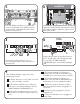
Slide the IC into the appropriate slot. Push the left and
right ejector handles inward to fully seat the IC. Using
a #1 Phillips screwdriver, tighten the captive screws in
both ejector handles.
6
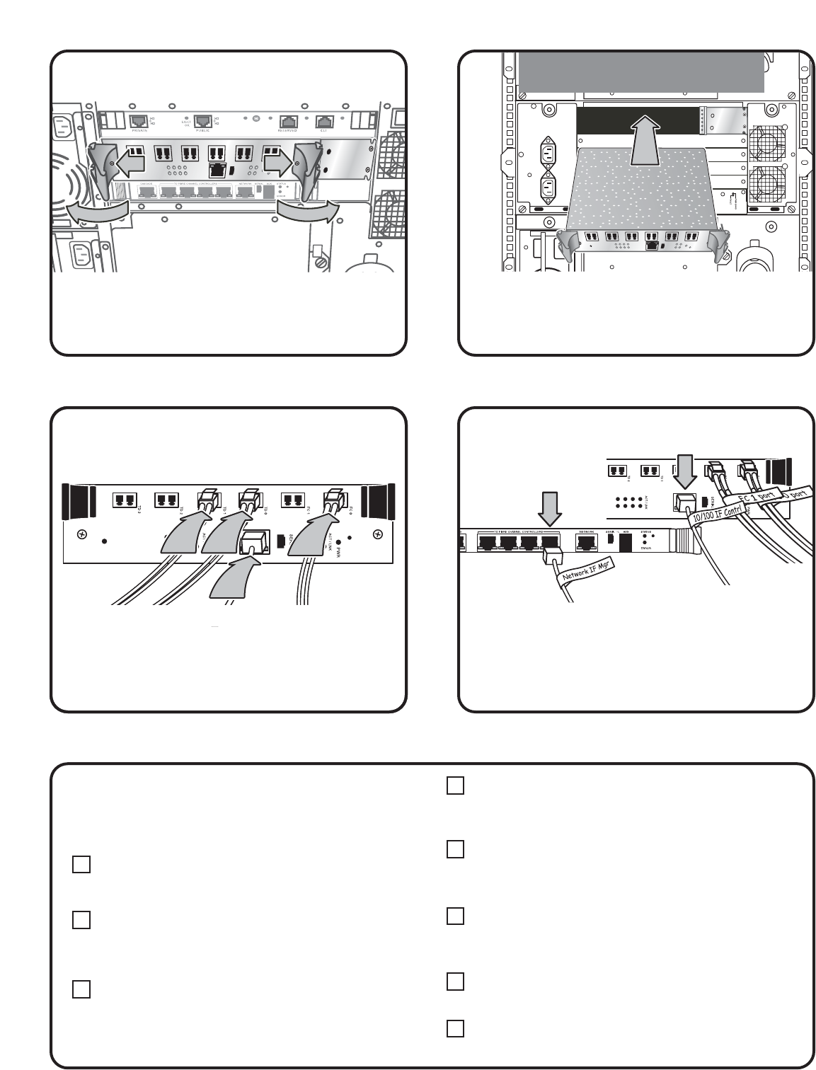
Plug the Ethernet cable into the Ethernet port on
the IC. Plug the other end of the Ethernet cable
into one of the TO FIBRE CHANNEL
CONTROLLERS ports on the Interface Manager
card.
Interface
Manager
Interface
Controller
877
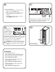
Reconnect the cables. Make sure you are
reconnecting the cables exactly as they were on
the original IC.
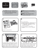
Use a #1 Phillips screwdriver to loosen the two
screws in the IC black ejector handles. Push the
ejector handles outward and then pull on both
handles to remove the IC.
After installing all library components, review
the following checklist:
1. All tape drives have one FC cable connected
to a port in a interface controller.
2. All interface controllers have one Ethernet
connection to the Interface Manager card (TO
FIBRE CHANNEL CONTROLLERS) port.
3. All interface controllers have one or two FC
connections to the SAN through the FC0 or FC1
ports.
4. The Interface Manager should have one
Ethernet connection from the CASCADE port to
the PUBLIC port on the library robotics controller.
5. The Interface Manager should have one
Ethernet connection from the NETWORK port to
an Ethernet port on your management station.
6. Each power supply on the base module or
tape drive expansion module is plugged into a
power strip.
7. Each power strip is plugged into a power
distribution unit.
8. Each power distribution unit is plugged into
an AC outlet.