
FW V06.XX/HAFM SW V08.02.00 HP StorageWorks SAN High Availability Planning Guide (AA-RS2DD-TE, July 2004)


Table Of Contents
- SAN HA Planning Guide
- Contents
- About this Guide
- Introduction to HP Fibre Channel Products
- Product Management
- Planning Considerations for Fibre Channel Topologies
- Fibre Channel Topologies
- Planning for Point-to-Point Connectivity
- Characteristics of Arbitrated Loop Operation
- Planning for Private Arbitrated Loop Connectivity
- Planning for Fabric-Attached Loop Connectivity
- Planning for Multi-Switch Fabric Support
- Fabric Topologies
- Planning a Fibre Channel Fabric Topology
- Fabric Topology Design Considerations
- FICON Cascading
- Physical Planning Considerations
- Port Connectivity and Fiber-Optic Cabling
- HAFM Appliance, LAN, and Remote Access Support
- Inband Management Access (Optional)
- Security Provisions
- Optional Features
- Configuration Planning Tasks
- Task 1: Prepare a Site Plan
- Task 2: Plan Fibre Channel Cable Routing
- Task 3: Consider Interoperability with Fabric Elements and End Devices
- Task 4: Plan Console Management Support
- Task 5: Plan Ethernet Access
- Task 6: Plan Network Addresses
- Task 7: Plan SNMP Support (Optional)
- Task 8: Plan E-Mail Notification (Optional)
- Task 9: Establish Product and HAFM Appliance Security Measures
- Task 10: Plan Phone Connections
- Task 11: Diagram the Planned Configuration
- Task 12: Assign Port Names and Nicknames
- Task 13: Complete the Planning Worksheet
- Task 14: Plan AC Power
- Task 15: Plan a Multi-Switch Fabric (Optional)
- Task 16: Plan Zone Sets for Multiple Products (Optional)
- Index
Planning Considerations for Fibre Channel Topologies
97SAN High Availability Planning Guide
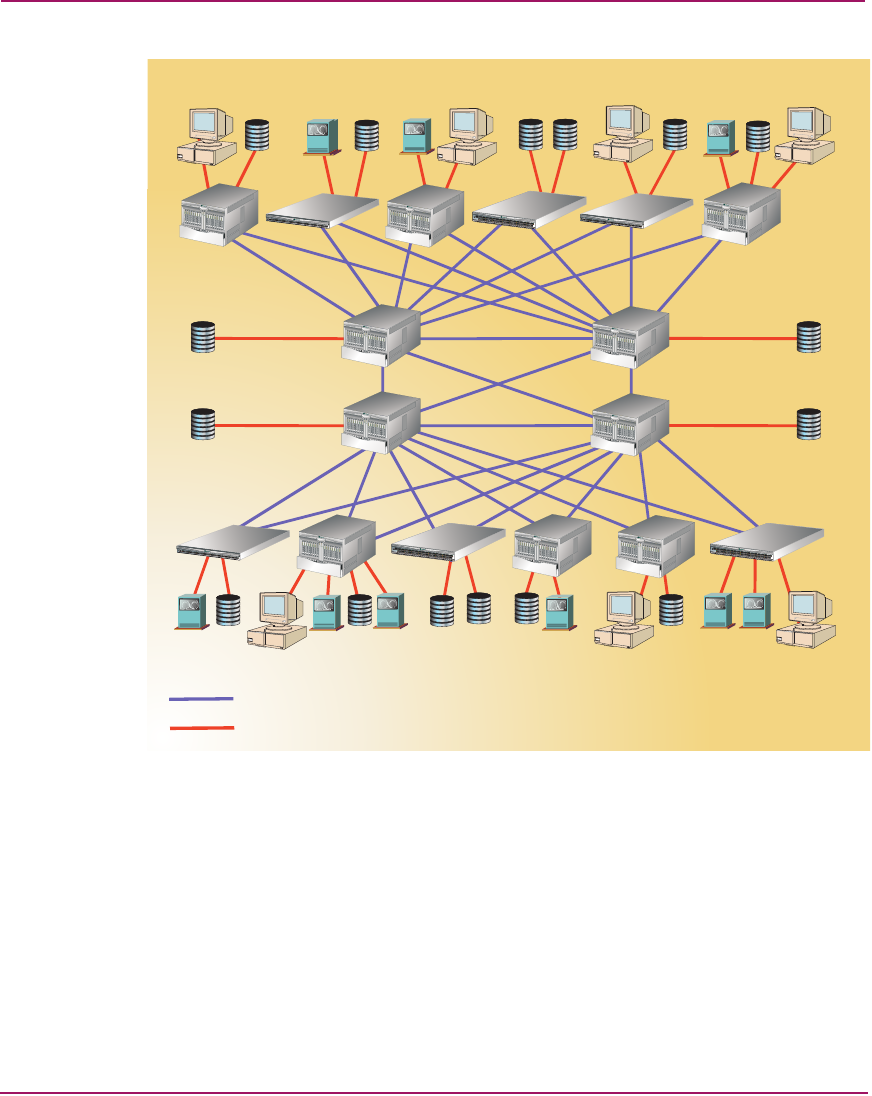
Figure 40: 4-by-12 Core-to-Edge fabric
A core-to-edge topology offers any-to-any device connectivity, and evenly
distributes traffic bandwidth throughout the fabric. The topology provides the
most flexible architecture to address fabric performance, traffic locality, data
integrity, connectivity, and scalability requirements.
The simplest core-to edge fabric has two or more core switching elements that
may or may not be connected (simple or complex). In a simple core topology, as
shown in Figure 39, core switches are not connected. In a complex core topology,
as shown in Figure 40, core switches are connected. The figure also illustrates a
topology where the core is a full-mesh fabric.
T
M
T
M
T
M
T
M
T
M
T
M
E
R
R
P
W
R
R
S
T
1
0
/
1
0
0
T
M
P
W
R
E
R
R
1
0
2
4
6
8
10
1
2
1
4
1
6
1
8
2
0
2
2
2
4
2
6
2
8
3
0
3
5
7
9
1
113
15
1
7
1
9
2
1
2
3
2
5
2
7
29
3
1
R
S
T
1
0
/100
T
M
E
R
R
P
W
R
R
S
T
1
0
/
1
0
0
T
M
T
M
E
R
R
P
W
R
R
S
T
1
0
/
1
0
0
T
M
P
W
R
E
R
R
1
0
2
4
6
8
1
0
1
2
1
4
1
6
1
8
20
2
2
2
4
2
6
2
8
30
3
5
7
9
11
1
3
15
17
1
9
2
1
2
3
25
2
7
29
3
1
R
S
T
10/
10
0
T
M
P
W
R
E
R
R
1
0
2
4
6
8
1
0
1
2
1
4
1
6
1
8
20
2
2
24
2
6
2
8
30
3
5
7
9
11
1
3
15
17
1
9
2
1
2
3
25
2
7
29
3
1
R
S
T
10/100
T
M
T
M
T
M
T
M
Interswitch Link
Fabric Connection
Tier 3 Devices
Edge
Switches
Tier 1
Devices
Edge
Switches
Core
Directors
Core
Directors
Tier 1
Devices
Tier 3 Devices