
FW V06.XX/HAFM SW V08.02.00 HP StorageWorks SAN High Availability Planning Guide (AA-RS2DD-TE, July 2004)


Table Of Contents
- SAN HA Planning Guide
- Contents
- About this Guide
- Introduction to HP Fibre Channel Products
- Product Management
- Planning Considerations for Fibre Channel Topologies
- Fibre Channel Topologies
- Planning for Point-to-Point Connectivity
- Characteristics of Arbitrated Loop Operation
- Planning for Private Arbitrated Loop Connectivity
- Planning for Fabric-Attached Loop Connectivity
- Planning for Multi-Switch Fabric Support
- Fabric Topologies
- Planning a Fibre Channel Fabric Topology
- Fabric Topology Design Considerations
- FICON Cascading
- Physical Planning Considerations
- Port Connectivity and Fiber-Optic Cabling
- HAFM Appliance, LAN, and Remote Access Support
- Inband Management Access (Optional)
- Security Provisions
- Optional Features
- Configuration Planning Tasks
- Task 1: Prepare a Site Plan
- Task 2: Plan Fibre Channel Cable Routing
- Task 3: Consider Interoperability with Fabric Elements and End Devices
- Task 4: Plan Console Management Support
- Task 5: Plan Ethernet Access
- Task 6: Plan Network Addresses
- Task 7: Plan SNMP Support (Optional)
- Task 8: Plan E-Mail Notification (Optional)
- Task 9: Establish Product and HAFM Appliance Security Measures
- Task 10: Plan Phone Connections
- Task 11: Diagram the Planned Configuration
- Task 12: Assign Port Names and Nicknames
- Task 13: Complete the Planning Worksheet
- Task 14: Plan AC Power
- Task 15: Plan a Multi-Switch Fabric (Optional)
- Task 16: Plan Zone Sets for Multiple Products (Optional)
- Index
Planning Considerations for Fibre Channel Topologies
72 SAN High Availability Planning Guide
Although the architectural limit of a Fibre Channel arbitrated loop is 125 devices,
32 or fewer devices should be attached to the switch to avoid adversely impacting
loop performance. In particular, avoid attaching an excess number of servers or
high-bandwidth storage devices.
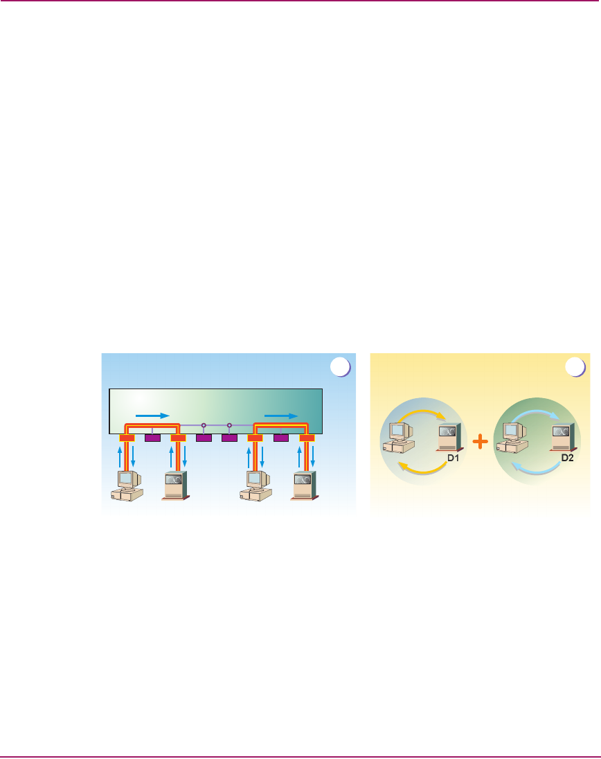
Switched Mode Operation
When set to switched mode (default setting), a loop switch enables frame
transmission through multiple point-to-point connected pairs. Switched mode
operation and its simplified logical equivalent are illustrated in Figure 29.
Part A of Figure 29 shows server S
1
connected to device D
1
through a switched
pair of H_Ports, communicating at 1.0625 Gbps. Server S
2
is connected to device
D
2
through a second switched pair of H_Ports, also communicating at 1.0625
Gbps. Because of opportunistic bandwidth sharing, the two switched pairs
effectively increase the switch bandwidth to 2.125 Gbps. The remaining switch
H_Ports (four ports) are available for switched connection to each other but
cannot communicate with servers S
1
and S
2
or devices D
1
and D
2
. Part (B) of
Figure 29 shows the logical equivalent of this arbitrated loop.
Figure 29: Switched mode operation and logical equivalent
Switched mode also allows independent operation of looplets of devices, each
connected through an unmanaged hub and each attached to a single switch
H_Port. Figure 30 shows 8 hubs, each connected to a switch H_Port and each
connected to a pair of devices (16 devices total). Each device pair forms a looplet
that communicates through a hub and connecting H_Port, and because of
opportunistic bandwidth sharing the looplets effectively increase the switch
bandwidth to 8.5 Gbps.
H_Ports
D1 D2
D2S2S1
D1
S1 S2
A
B
Logical Equivalent
Loop Switch