
FW V06.XX/HAFM SW V08.02.00 HP StorageWorks SAN High Availability Planning Guide (AA-RS2DD-TE, July 2004)


Table Of Contents
- SAN HA Planning Guide
- Contents
- About this Guide
- Introduction to HP Fibre Channel Products
- Product Management
- Planning Considerations for Fibre Channel Topologies
- Fibre Channel Topologies
- Planning for Point-to-Point Connectivity
- Characteristics of Arbitrated Loop Operation
- Planning for Private Arbitrated Loop Connectivity
- Planning for Fabric-Attached Loop Connectivity
- Planning for Multi-Switch Fabric Support
- Fabric Topologies
- Planning a Fibre Channel Fabric Topology
- Fabric Topology Design Considerations
- FICON Cascading
- Physical Planning Considerations
- Port Connectivity and Fiber-Optic Cabling
- HAFM Appliance, LAN, and Remote Access Support
- Inband Management Access (Optional)
- Security Provisions
- Optional Features
- Configuration Planning Tasks
- Task 1: Prepare a Site Plan
- Task 2: Plan Fibre Channel Cable Routing
- Task 3: Consider Interoperability with Fabric Elements and End Devices
- Task 4: Plan Console Management Support
- Task 5: Plan Ethernet Access
- Task 6: Plan Network Addresses
- Task 7: Plan SNMP Support (Optional)
- Task 8: Plan E-Mail Notification (Optional)
- Task 9: Establish Product and HAFM Appliance Security Measures
- Task 10: Plan Phone Connections
- Task 11: Diagram the Planned Configuration
- Task 12: Assign Port Names and Nicknames
- Task 13: Complete the Planning Worksheet
- Task 14: Plan AC Power
- Task 15: Plan a Multi-Switch Fabric (Optional)
- Task 16: Plan Zone Sets for Multiple Products (Optional)
- Index
Planning Considerations for Fibre Channel Topologies
70 SAN High Availability Planning Guide
between device D
1
and server S
1
travels through a loop that consists of all eight
H_Ports, device D
1
, device D
2
, and server S
1.
Each H_Port not participating in the
communication pair and the NL_Port on device D
2
provide a repeater function
that allows frames to pass around the loop at the full switch bandwidth.
Part B of Figure 27 shows the logical equivalent of this arbitrated loop. When
frame transmission between device D
1
and server S
1
completes, the loop circuit
closes and other ports attached to initiating devices arbitrate for loop access.
When operating in shared mode, the switch is a serially reusable resource that
provides service access to all ports on the loop. Access is granted by successful
arbitration. When arbitration is won by a device, the loop is busy and other
arbitrating devices must wait for loop access.
Device attachment and loop construction are not limited to the eight switch
H_Ports. Through the use of cascaded unmanaged hubs, the Fibre Channel
architectural limit of 125 FC-AL devices can attach to the switch. For example,
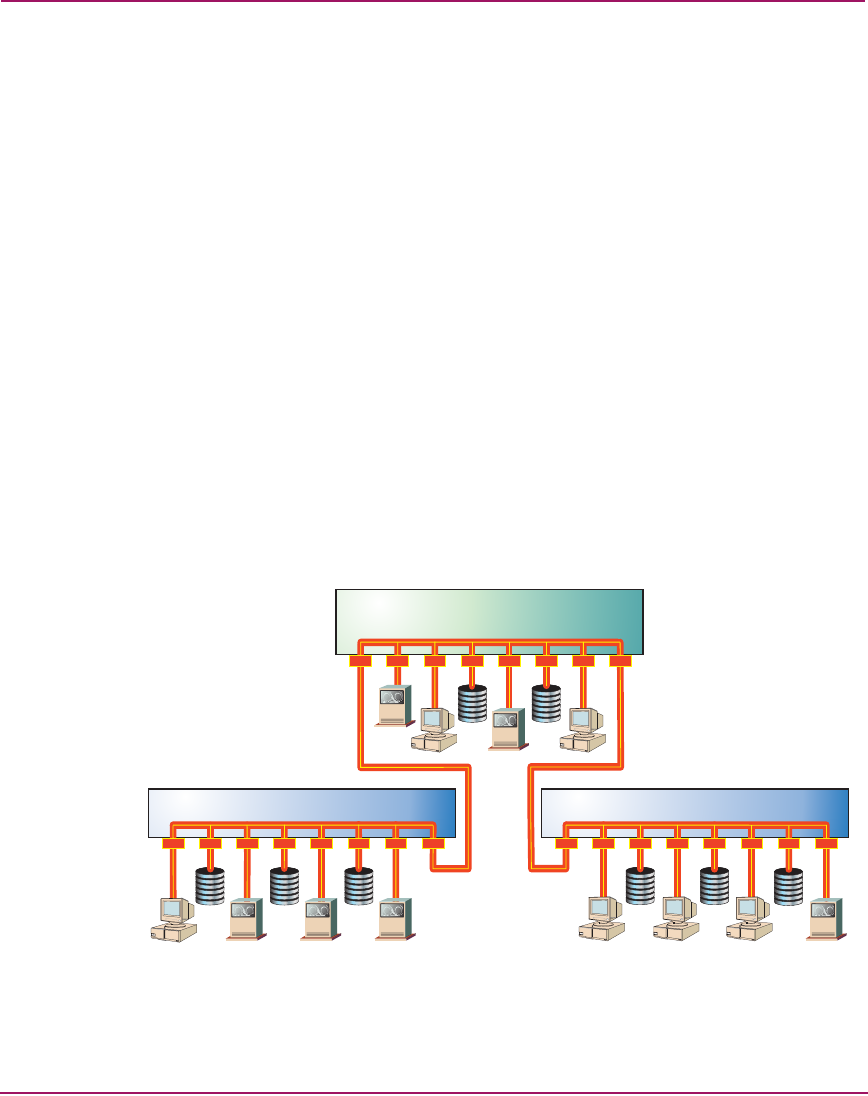
Figure 28 shows a private loop composed of a loop switch, 20 FC-AL devices,
and two unmanaged hubs.
Hubs are cascaded through H_Port-to-H_Port connections (one port per switch or
hub). Server S
1
communicates with device D
1
through a loop that includes
H_Ports on all three hubs and NL_Ports on the remaining 18 devices.
Figure 28: 20-Device private arbitrated loop
S1
Hub Hub
D1
H_Ports
H_Ports
Loop Switch
Loop Switch