
FW V06.XX/HAFM SW V08.02.00 HP StorageWorks SAN High Availability Planning Guide (AA-RS2DD-TE, July 2004)


Table Of Contents
- SAN HA Planning Guide
- Contents
- About this Guide
- Introduction to HP Fibre Channel Products
- Product Management
- Planning Considerations for Fibre Channel Topologies
- Fibre Channel Topologies
- Planning for Point-to-Point Connectivity
- Characteristics of Arbitrated Loop Operation
- Planning for Private Arbitrated Loop Connectivity
- Planning for Fabric-Attached Loop Connectivity
- Planning for Multi-Switch Fabric Support
- Fabric Topologies
- Planning a Fibre Channel Fabric Topology
- Fabric Topology Design Considerations
- FICON Cascading
- Physical Planning Considerations
- Port Connectivity and Fiber-Optic Cabling
- HAFM Appliance, LAN, and Remote Access Support
- Inband Management Access (Optional)
- Security Provisions
- Optional Features
- Configuration Planning Tasks
- Task 1: Prepare a Site Plan
- Task 2: Plan Fibre Channel Cable Routing
- Task 3: Consider Interoperability with Fabric Elements and End Devices
- Task 4: Plan Console Management Support
- Task 5: Plan Ethernet Access
- Task 6: Plan Network Addresses
- Task 7: Plan SNMP Support (Optional)
- Task 8: Plan E-Mail Notification (Optional)
- Task 9: Establish Product and HAFM Appliance Security Measures
- Task 10: Plan Phone Connections
- Task 11: Diagram the Planned Configuration
- Task 12: Assign Port Names and Nicknames
- Task 13: Complete the Planning Worksheet
- Task 14: Plan AC Power
- Task 15: Plan a Multi-Switch Fabric (Optional)
- Task 16: Plan Zone Sets for Multiple Products (Optional)
- Index
Physical Planning Considerations
137SAN High Availability Planning Guide
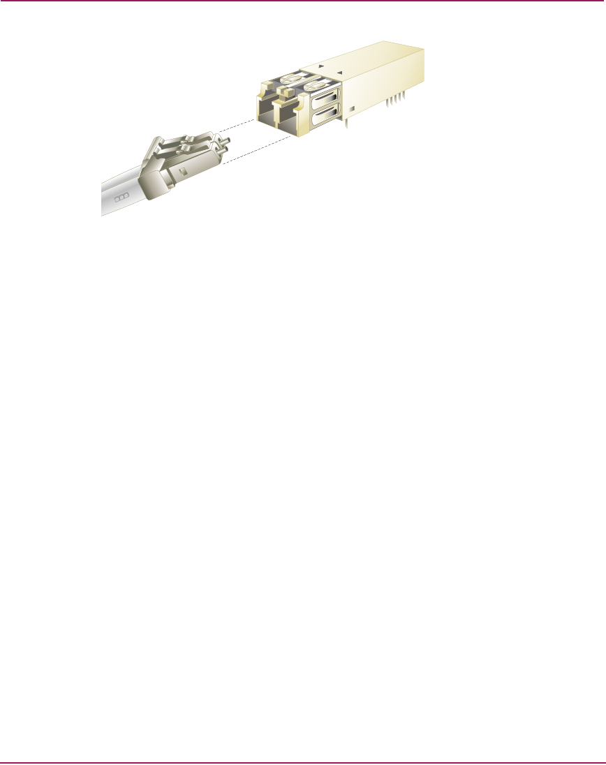
Figure 54: SFP transceiver and LC duplex connector
Routing Fiber-Optic Cables
Follow a logical plan for routing fiber-optic cables to avoid confusing connections
during installation and operation. Route cables from the access holes at the bottom
or top of the equipment rack, and then to director and switch ports.
Leave enough slack in the cables to allow cable movement for UPM card or
optical transceiver removal and replacement or possible rerouting of the cable to
another port.
When routing fiber-optic cables and estimating cable lengths, consider:
■ Cable routing inside the equipment rack to different port locations and
installation position of the director or switch (top or bottom of the rack). Plan
for 1.0 meter (39.37 inches) of extra cable for routing through restraint
mechanisms and rerouting cables to other ports.
■ Cable routing outside the equipment rack. Plan for 1.5 meters (5 feet) of cable
outside the rack to provide slack for service clearance, limited rack
movement, and inadvertent cable pulls.
■ Cabling distance to servers, storage devices, and other fabric elements
(for multi-switch fabric support).
The need for additional fiber-optic cabling could grow rapidly. More cables may
be required for connections to additional servers or storage devices or for
connections to additional fabric elements as a multi-switch fabric is developed.
The director or switch may need to be moved for more efficient connection to