
FW V06.XX/HAFM SW V08.02.00 HP StorageWorks SAN High Availability Planning Guide (AA-RS2DD-TE, July 2004)


Table Of Contents
- SAN HA Planning Guide
- Contents
- About this Guide
- Introduction to HP Fibre Channel Products
- Product Management
- Planning Considerations for Fibre Channel Topologies
- Fibre Channel Topologies
- Planning for Point-to-Point Connectivity
- Characteristics of Arbitrated Loop Operation
- Planning for Private Arbitrated Loop Connectivity
- Planning for Fabric-Attached Loop Connectivity
- Planning for Multi-Switch Fabric Support
- Fabric Topologies
- Planning a Fibre Channel Fabric Topology
- Fabric Topology Design Considerations
- FICON Cascading
- Physical Planning Considerations
- Port Connectivity and Fiber-Optic Cabling
- HAFM Appliance, LAN, and Remote Access Support
- Inband Management Access (Optional)
- Security Provisions
- Optional Features
- Configuration Planning Tasks
- Task 1: Prepare a Site Plan
- Task 2: Plan Fibre Channel Cable Routing
- Task 3: Consider Interoperability with Fabric Elements and End Devices
- Task 4: Plan Console Management Support
- Task 5: Plan Ethernet Access
- Task 6: Plan Network Addresses
- Task 7: Plan SNMP Support (Optional)
- Task 8: Plan E-Mail Notification (Optional)
- Task 9: Establish Product and HAFM Appliance Security Measures
- Task 10: Plan Phone Connections
- Task 11: Diagram the Planned Configuration
- Task 12: Assign Port Names and Nicknames
- Task 13: Complete the Planning Worksheet
- Task 14: Plan AC Power
- Task 15: Plan a Multi-Switch Fabric (Optional)
- Task 16: Plan Zone Sets for Multiple Products (Optional)
- Index
Planning Considerations for Fibre Channel Topologies
127SAN High Availability Planning Guide
b. If required, click the Hardware tab. The Hardware View (Figure 19)
displays. Verify that the status bar at the bottom left corner of the window
displays a green circle, indicating director or switch status is operational.
If a problem is indicated, go to MAP 0000: Start MAP in the
product-specific Installation and Service Manual.
c. Verify operation of non-cascaded FICON applications at each director or
switch.
3. Verify ISL operation — Ensure ISL connectivity between fabric elements.
Perform this step at each director or switch.
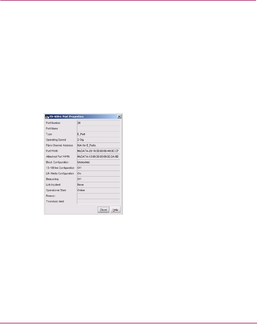
a. In the Element Manager application’s Hardware View, double-click the
graphical E_Port connector used for the ISL. The Port Properties dialog
box displays (Figure 50).
Figure 50: Port Properties Dialog Box
b. Ensure that the Link Incident field displays None and the Reason field is
blank. If an ISL segmentation or other problem is indicated, refer to the
diagnostics information described in the appropriate service manual for
your Director or Edge Switch.
c. Click Close to close the dialog box and return to the Hardware View.
4. Install SANtegrity Binding on fabric elements — Configure and enable the
SANtegrity Binding feature at each director or switch as follows:
a. In the Element Manager application, install the SANtegrity Binding PFE
key. Refer to the installation instructions in the appropriate installation
manual for your Director or Edge Switch.