
FW V06.XX/HAFM SW V08.02.00 HP StorageWorks SAN High Availability Planning Guide (AA-RS2DD-TE, July 2004)


Table Of Contents
- SAN HA Planning Guide
- Contents
- About this Guide
- Introduction to HP Fibre Channel Products
- Product Management
- Planning Considerations for Fibre Channel Topologies
- Fibre Channel Topologies
- Planning for Point-to-Point Connectivity
- Characteristics of Arbitrated Loop Operation
- Planning for Private Arbitrated Loop Connectivity
- Planning for Fabric-Attached Loop Connectivity
- Planning for Multi-Switch Fabric Support
- Fabric Topologies
- Planning a Fibre Channel Fabric Topology
- Fabric Topology Design Considerations
- FICON Cascading
- Physical Planning Considerations
- Port Connectivity and Fiber-Optic Cabling
- HAFM Appliance, LAN, and Remote Access Support
- Inband Management Access (Optional)
- Security Provisions
- Optional Features
- Configuration Planning Tasks
- Task 1: Prepare a Site Plan
- Task 2: Plan Fibre Channel Cable Routing
- Task 3: Consider Interoperability with Fabric Elements and End Devices
- Task 4: Plan Console Management Support
- Task 5: Plan Ethernet Access
- Task 6: Plan Network Addresses
- Task 7: Plan SNMP Support (Optional)
- Task 8: Plan E-Mail Notification (Optional)
- Task 9: Establish Product and HAFM Appliance Security Measures
- Task 10: Plan Phone Connections
- Task 11: Diagram the Planned Configuration
- Task 12: Assign Port Names and Nicknames
- Task 13: Complete the Planning Worksheet
- Task 14: Plan AC Power
- Task 15: Plan a Multi-Switch Fabric (Optional)
- Task 16: Plan Zone Sets for Multiple Products (Optional)
- Index
Planning Considerations for Fibre Channel Topologies
104 SAN High Availability Planning Guide
Performance Tuning
When designing or tuning a fabric for performance, it is critical to understand
application I/O characteristics so that:
■ Device output in Gbps does not oversubscribe ISLs, leading to fabric
congestion.
■ Device output in IOPS does not result in a connectivity scheme that exceeds
fan-out ratios, leading to port congestion.
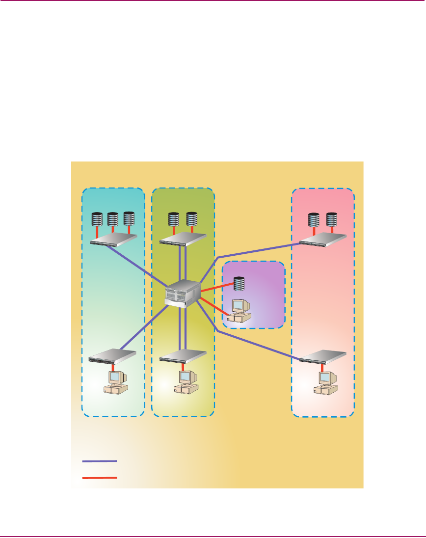
Figure 44 illustrates performance tuning for a simple fabric using appropriate ISL
connectivity, device locality, and fan-out regions for device connectivity.
Figure 44: Fabric performance tuning
Interswitch Link
Fabric Connection
6,000 IOPS
Tier 2 Storage
P
W
R
E
R
R
1
0
2
4
6
8
1
0
1
2
1
4
1
6
1
8
2
0
2
2
2
4
2
6
2
8
3
0
3
5
7
9
11
1
3
1
5
1
7
1
9
2
1
2
3
2
5
2
7
2
9
3
1
R
S
T
1
0
/
1
0
0
T
M
E
R
R
P
W
R
R
S
T
1
0
/
1
0
0
T
M
E
R
R
P
W
R
R
S
T
1
0
/
1
0
0
T
M
E
R
R
P
W
R
R
S
T
1
0
/
1
0
0
T
M
E
R
R
P
W
R
R
S
T
1
0
/
1
0
0
T
M
E
R
R
P
W
R
R
S
T
1
0
/
1
0
0
T
M
30 Mbps
2,000 IOPS
20 MBps
1,500 IOPS
10 MBps
1,000 IOPS
11 to 1 Fan-Out Region
11,000 IOPS
11 Total
Servers
6 Total
Servers
3 Total
Servers
Local Tier 1 Devices
40 Mbps
2,000 IOPS
2,000 IOPS
T
M
6 to 1 Fan-Out Region
9,000 IOPS
3 to 1 Fan-Out Region
6,000 IOPS
Tier 2 Servers