
FW 07.00.00/HAFM SW 08.06.00 McDATA Products in a SAN Environment Planning Manual (620-000124-500, April 2005)


3
Planning Considerations for Fibre Channel Topologies
3-57
Planning Considerations for Fibre Channel Topologies
7. Verify FICON devices are still logged in - Maximize the Element
Manager application. Inspect the Node List View and verify
FICON devices (channels and control units inspected in step 5)
are still logged in to each director or switch.
8. Change switch binding enforcement if required - If the SAN
environment is volatile (characterized by a high volume of optical
cable connects, disconnects, and movement), change switch
binding enforcement to restrict E_Ports only.
a. At the Element Manager application, click the Hardware tab.
At the Hardware View, select Switch Binding, then Change State
from the Configure menu. The Switch Binding - State Change
dialog box displays.
b. Ensure the Enable Switch Binding check box is checked
(enabled).
c. Select (click) the Restrict E_Ports radio button to restrict
connections from specific fabric elements to E_Ports. WWNs
can be added to the membership list to allow fabric element
connection and removed from the list to prohibit fabric
element connection. Devices are allowed to connect to any
F_Port or FL_Port without restriction.
d. Click Activate to close the dialog box and enforce the
connection policy.
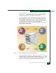
9. Update channel path and control unit definitions - A cascaded
FICON environment requires channel entry switch and link
address updates to the input/output configuration program
(IOCP) as follows:
a. In the IOCP, define an entry switch ID in the SWITCH
keyword of the channel path identifier (CHPID) definition.
NOTE: An entry switch is a fabric director or switch connected to the
FICON channel of a zSeries processor and a second fabric director or
switch.
b. In the IOCP, define a 2-byte link address (consisting of a
switch (or domain) address and port address) for the cascaded
switch in the LINK keyword of the control unit (CNTLUNIT)
definition.