
FW 07.00.00/HAFM SW 08.06.00 McDATA Products in a SAN Environment Planning Manual (620-000124-500, April 2005)

3
Planning Considerations for Fibre Channel Topologies
3-35
Planning Considerations for Fibre Channel Topologies
When designing a core-to-edge fabric, servers and storage devices
that support such bandwidth-intensive applications should be
attached to core directors as Tier 1 devices. As a best practices policy
(assuming 1.0625 Gbps ISLs), devices that generate a sustained
output of 35 MBps or higher are candidates for Tier 1 connectivity.
FICON devices also must use Tier 1 connectivity. For additional
information, refer to FCP and FICON in a Single Fabric.
Device Fan-Out Ratio The output of most host devices is bursty in nature, most devices do
not sustain full-bandwidth output, and it is uncommon for the output
of multiple devices to peak simultaneously. These variations are why
multiple hosts can be serviced by a single storage port. This device
sharing leads to the concept of fan-out ratio.
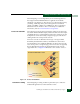
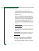
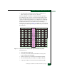
Device fan-out ratio is defined as the storage or array port IOPS
divided by the attached host IOPS, rounded down to the nearest
whole number. A more simplistic definition for device fan out is the
ratio of host ports to a single storage port. Fan-out ratios are typically
device dependent. In general, the maximum device fan-out ratio
supported is 12 to 1. Figure 3-14 illustrates a fan-out ratio of 10 to 1.
Figure 3-14 Device Fan-Out Ratio
Performance Tuning When designing or tuning a fabric for performance, it is critical to
understand application I/O characteristics so that:
T
M
T
M
Interswitch Link
Fabric Connection
1,000 IOPS
1,000 IOPS
1,000 IOPS
1,000 IOPS
1,000 IOPS
1,000 IOPS
10,000 IOPS
1,000 IOPS
1,000 IOPS
1,000 IOPS
1,000 IOPS
Device Fan-Out Ratio: 10 to 1