
HP StoreOnce B6200 Maintenance and Service Guide (February, 2014)


NOTE:
• The HP B6200 Backup System can only be installed in an HP B6000 rack.
• An HP B6000 rack should only be used for HP B6200 Backup Systems and supported storage
expansion shelves.
• Do not install additional units, such as Ethernet network switches, in the rack. You will not be
able to expand storage, if you do so.
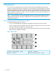
• The base couplet is always located in shelves 7 to 14 inclusive.
• When installing a second couplet, it is located in shelves 27 to 34 inclusive. Capacity upgrade
kits can then be added in pairs above and below the couplet.
• Two-rack systems must be located next to each other to ensure there are no problems with
cable lengths.
Hardware components
Field replacement components may be replaced within any of the following hardware elements:
• The DL380 G7 ProLiant servers that are used for the nodes; there are two nodes in each
couplet (and up to four couplets in a cluster). See Maintaining server (node)
components (page 22).
• The P2000 MSA/Controllers that provide the disk storage; there are two P2000 master
controller shelves in each couplet and up to 3 pairs of P2000 JBOD shelves may be added
to a couplet to expand storage. See Maintaining P2000/MSA array controller
components (page 29).
• The internal network switches that support the internal 1GbE and 10GbE networks: Rack 1
has two E6600–24G-4XG network switches, Rack 2 has two E6600ml-24XG network switches.
See Maintaining internal network switches (page 36).
CAUTION: In all cases when replacing hardware the following precautions apply:
• The HP B6200 Backup System often requires special shutdown and power up sequences prior
to and after replacing hardware. Please do not assume that the hardware can be hotplugged,
but check the relevant sections in this document for further instructions.
• Make sure all replacement components are running the correct firmware revision. This is listed
in Firmware revisions (page 13) and then updated, as appropriate, in all release notes that
accompany any software upgrades.
• If replacement activities require you to disconnect cables or remove hard disks, make sure
everything is reconnected in exactly the same way to support the original failover cabling and
disk configuration.
Fault LEDs
Care must be taken to replace the correct component. Many components also have Fault LEDs that
will help you isolate the problem. Be sure to check the Fault LEDs on the individual components,
such as I/O modules on the P2000 Controller or HDDs, as well as working with the information
on the Hardware Problem Report page of the GUI (see How are hardware problems
notified (page 18)).
Online or offline during maintenance activity?
The HP B6200 Backup System has dual paths and cabling to enable resilience in the event of a
problem on an individual component. This means that care must be taken when replacing
Hardware components 7