
HP StoreOnce 6500 Backup Installation Planning and Preparation Guide


5 Fibre Channel connection
The physical FC connection to the HP StoreOnce Backup System is straightforward; there are four
FC ports per node. However, care must be taken to ensure there is no single point of failure in
switch or fabric zoning that will negate the failover capabilities of the HP StoreOnce Backup System
and its autonomic restart ability.
Conformance to the following rules will help to ensure successful failover
• Fibre Channel switches used with HP StoreOnce must support NPIV. The preferred topology
uses NPIV (N_Port ID Virtualisation). Direct attach (private loop) and direct attach (point to
point) topologies are not supported. For a full list see http://www.hp.com/go/ebs.
NOTE: The HP Brocade SAN Switches support NPIV natively but the Cisco SAN Switches
require that it be turned on on each port used
• Use WWPN zoning (rather than port based). This keeps the backup/restore environment
simple and less susceptible to the effects of changing or problematic SANs.
• Ensure that there are two switches in each fabric.
• In a single fabric configuration ensure the equivalent FC ports from each node in a couplet
are presented to the same FC switch.
• In a dual fabric configuration ensure the equivalent FC ports from each node in a couplet are
presented to the same fabric. They should present to separate switches within the fabric.
• Ensure the D2D diagnostic device WWNs (these will be seen in the switch name server and
are associated with the physical ports) are not included in any fabric zones and, therefore,
not presented to any hosts. This avoids confusion on the host as to which port is used for the
Media changer.
Please see the HP StoreOnce Backup System Concepts and Configuration Guidelines for further
information and configuration examples.
Connecting the Fibre Channel cables (optional)
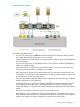
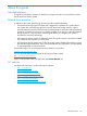
If VTL libraries are to be used, connect cables to the FC ports as shown in the diagram below.
StoreOnce Catalyst is also supported over Fibre Channel infrastructure, but is not automatically
enabled. Please consult your HP Sales Representative if you wish to use this feature.
Figure 3 Fibre Channel cabling to each node
Identified as FC Port 1 on the StoreOnce GUI1.
Identified as FC Port 2 on the StoreOnce GUI2.
Identified as FC Port 3 on the StoreOnce GUI3.
Identified as FC Port 4 on the StoreOnce GUI4.
26 Fibre Channel connection