
HP StoreOnce B6200 Maintenance and Service Guide (February, 2014)


10. You may now plug in all the ethernet cables into the switches. If you require additional
assistance to show where the cables go, please see the Installation & Configuration Training
Module.
Switch cabling diagrams
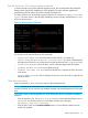
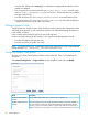
Figure 14 Example cable label, internal network switch
The factory uses combinations of the following terminology for labelling cables.
• R<n>Sw<X>, where R<n> is the Rack number, 1 or 2, and Sw is the internal network switch
within the rack, which may be A or B.
• R<n>C<n>, where R<n> is the Rack number, 1 or 2, and C<n> is the Couplet number within
the cluster, which may be 1 to 4.
• Node<X>, where Node is the node within the couplet, which may be A or B.
• P2K<X>, where P2K is the P2000 controller within the couplet, which may be A or B.
• Slot<n>Port<n>, which identifies the slot or card number and port number to which a cable
should be connected
For example:
• A cable plugged into Rack 1, Switch A, Port 1 would be labeled: R1SwA Port1
• A cable plugged into Rack 1, Couplet 1, ControllerA of NodeB would be labeled: R1C1
P2KB CtlrA
NOTE: The cable colors represent length of cables, and do not represent any specific route or
connection within the internal network.
Switch cabling diagrams 41