
HP P6000 Continuous Access Implementation Guide (T3680-96431, August 2012)
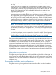
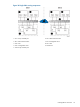
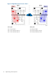
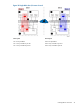
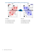
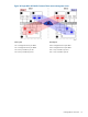
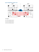
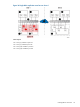
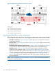

Figure 37 Single-fabric replication zone fan-out: sheet 2
Zone 11 ports
Site 1 Array (10) controller A port FP2
Site 1 Array (10) controller B port FP2
Site 2 Array (5) controller A port FP2
Site 2 Array (5) controller B port FP2
Recommended dual-fabric zoning configurations
This is a high availability configuration consisting of two switches per site, which creates two distinct
extended fabrics that span the two sites. This configuration eliminates the SPOF for host I/O traffic.
• Dual-fabric components—Figure 38 (page 81) shows the various components that comprise
the dual-fabric topology.
• Host I/O zones—Figure 39 (page 82) and Figure 40 (page 83) show the ports used to create
the host I/O zones.
• HP P6000 Command View management zones—Figure 41 (page 84) through Figure 44 (page
87) show the ports used to create the HP P6000 Command View management zones.
• Replication zones—Figure 45 (page 88) shows the ports used to create the HP P6000
Continuous Access replication zones. Figure 46 (page 89) and Figure 47 (page 90) show
replication zones when array system fan-out is used. Figure 48 (page 91) and Figure 49 (page
92) show replication zones used to create port isolation when array system fan-in or fan-out
is used in a configuration that includes an EVA3000/5000. Figure 50 (page 93) and
Figure 51 (page 94) show the replication zones when using a 4-port controller pair and an
8-port controller pair.
NOTE: See “FCIP gateway zoning configurations” (page 95) if you are creating a dual-fabric
configuration using FCIP gateways.
80 Implementing remote replication