HP StorageWorks XP Command View Advanced Edition software server administrator guide for Device Manager and Provisioning Manager (web version) Abstract This guide describes network and server configuration, system requirements, maintenance and troubleshooting, and CIM/WBEM integration for HP StorageWorks XP Command View Advanced Edition Device Manager and XP Provisioning Manager server software.
Legal and notice information © Copyright 2008, 2010 Hewlett-Packard Development Company, L.P. Confidential computer software. Valid license from HP required for possession, use or copying. Consistent with FAR 12.211 and 12.212, Commercial Computer Software, Computer Software Documentation, and Technical Data for Commercial Items are licensed to the U.S. Government under vendor's standard commercial license. The information contained herein is subject to change without notice.
Contents Contents 1 Overview 1-1 System configuration...................................................................................................................................... 8 1-2 Network configuration .................................................................................................................................. 10 1-2-1 Common security risks ........................................................................................................................
Contents 3 Settings required for managing user accounts 3-1 Setting password conditions for user accounts............................................................................................ 75 3-2 Settings for locking user accounts ............................................................................................................... 76 3-2-1 Settings for automatic locking..............................................................................................................
Contents 8-1 Before controlling the Device Manager server ........................................................................................... 127 8-2 Starting the Device Manager server........................................................................................................... 128 8-3 Stopping the Device Manager server.........................................................................................................
Contents A-2-21 server.base.home ........................................................................................................................... 189 A-2-22 server.horcmconfigfile.hostname .................................................................................................... 189 A-2-23 server.base.initialsynchro................................................................................................................ 189 A-2-24 server.cim.agent..................................
Contents A-9-1 customizedsnmptrap.customizedSNMPTrapEnable......................................................................... 202 A-9-2 customizedsnmptrap.customizelist ................................................................................................... 203 A-10 Device Manager mainframe host agent properties.................................................................................. 203 A-10-1 host.mf.agent.connection.timeout .......................................................
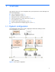
Overview 1 Overview This chapter describes the system configuration and system requirements for Device Manager and XP Provisioning Manager.
Overview A TCP/IP network must be used to connect a management server to management clients, and the management server to storage subsystems. Also, a Fibre Channel SAN must be configured between a host and a storage subsystem. The important configuration components in the above figure are as follows: Management server A management server is a computer on which the Device Manager server and the XP Provisioning Manager server are running.
Overview CLI CLI is text-based interface supported by Device Manager. Using CLI enables you to perform certain tasks (such as the initial installation of a system or applying the same changes to settings in many locations) more efficiently. For details on the computer requirements for using CLI and how to use it, see the HP StorageWorks XP Command View Advanced Edition software Device Manager CLI user guide.
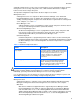
Overview The following figure illustrates an incorrect LAN connection. Figure 1-2 Incorrect XP series disk arrays LAN connection 1-2-1 Common security risks System administrators frequently separate production LANs from management LANs. In such cases, management LANs act as a separate network, which isolates management traffic from a production network and reduces the risk of security-related threats.
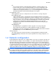
Overview a different LAN that has a different firewall. The firewall contains strict access rules that allow the management servers to be accessed only by Device Manager clients or by specified management application clients. The following figure illustrates a separate management LAN with a firewall configuration.
Overview Manager by a firewall. The firewall's rules allow a storage subsystem to be accessed only by the Device Manager server or by any other required management application. Management clients accessing Device Manager are not allowed to pass traffic through the firewall to directly talk to a managed storage subsystem, but can directly participate in management operations via Device Manager or a management application.
Overview actually act as the gateway between the production LAN and the management LAN, and there is no additional firewall, you must be very sure that the server itself will not route traffic between the two networks. This configuration is the third most secure, and is more flexible than either the most or second-most secure configurations. While it protects the devices under management, it does not protect the management application servers themselves.
Overview NOTE: This configuration may be a requirement if the implementation cannot accommodate a management LAN. The following figure illustrates a flat network. Figure 1-6 Least secure configuration: flat network 1-3 Management server requirements This section describes the management server requirements.
Overview Table 1-2 Usable management server OSs (Windows) OS Edition Service pack Cluster environment support IPv6 environment support Windows Server 2003 (x64) Datacenter x64 Edition Enterprise x64 Edition Standard x64 Edition SP2 -- Y Windows Server 2003 R2 (x86) Datacenter Edition Enterprise Edition Standard Edition SP2 Y Y Windows Server 2003 R2 (x64) Datacenter x64 Edition Enterprise x64 Edition Standard x64 Edition SP2 -- Y Windows Server 2008 (x86) * Datacenter 32-bit Edition Da
Overview Table 1-2 Usable management server OSs (Windows) OS Edition Service pack Cluster environment support IPv6 environment support Windows Server 2008 R2 (IPF) * for Itanium-based Systems No SP -- -- Windows Server 2008 R2 (x64) * Datacenter Edition Enterprise Edition Standard Edition No SP -- Y Windows XP Professional SP2 -- -- SP3 -- -- No SP -- Y SP1 -- Y SP2 -- Y Windows Vista (x86) Business Enterprise Ultimate Windows 7 (x86) Enterprise Edition Professional Editi
Overview Table 1-3 Virtual machine OSs on which the Device Manager server can run (Windows) Virtual machine Virtualization software VMware ESX1 Hyper-V2 HP Integrity VM3 Windows Server Datacenter SP2 2003 R2 Edition (x86) Enterprise Edition Standard Edition Y Y -- Windows Server Datacenter x64 2003 R2 Edition (x64) Enterprise x64 Edition Standard x64 Edition Y Y -- Y Y -- SP2 Y Y -- No SP Y Y Y SP2 Y Y -- Y Y -- SP2 Y Y -- No SP Y Y -- OS Edition Service pack SP2 No
Overview Table 1-3 Virtual machine OSs on which the Device Manager server can run (Windows) Virtual machine Virtualization software VMware ESX1 Hyper-V2 HP Integrity VM3 Windows Server Datacenter No SP 2008 R2 Edition (x64) Enterprise Edition Standard Edition Y Y -- Windows XP SP2 Y -- -- SP3 Y -- -- No SP Y -- -- SP1 Y -- -- SP2 Y -- -- OS Windows Vista (x86) Edition Professional Business Enterprise Ultimate Service pack Windows 7 (x86) Enterprise Edition Professional Ed
Overview Table 1-4 Computer requirements (Windows) Item Requirements Physical memory Minimum: 512 MB Recommended: At least 1 GB1 Disk space Minimum: 4 GB Recommended: At least 5 GB Monitor XGA (1024 x 768 resolution) or higher. LAN card 10/100 Ethernet LAN card If the computer and the LAN cable are compatible with Gigabit Ethernet, you can use a Gigabit-class card. CD drive None Prerequisite program J2SE Java Runtime Environment 5.0.xx (xx: 03 or later)2 Microsoft Windows Installer 3.
Overview Table 1-5 Virtual memory requirements for each product (Windows) Product name Virtual memory requirement (MB) Device Manager1 1,024 XP Provisioning Manager (Included in Device Manager) XP Tiered Storage Manager 600 2 XP Replication Manager 100 NOTE: If you plan to install Device Manager, XP Tiered Storage Manager, and XP Replication Manager, and if 1,000 MB of virtual memory is already used by the OS and other programs, you must secure more than 3,224 MB of virtual memory.
Overview Table 1-6 Installation folders and required disk space (in Windows) Item Default installation folder Required disk space Output folder for common trace log files 2, 3 program-filesfolder\Hitachi\HNTRLib2\spool 1.0 MB A temporary folder 4 A folder specified by the environment variable TMP 0.3 GB NOTE: If the architecture is x86, program-files-folder and common-program-files-folder are the folders specified in the Windows environment variables %ProgramFiles% and %CommonProgramFiles%.
Overview Table 1-7 Usable management server OSs (Linux) OS Version Architecture Cluster environment support IPv6 environment support Red Hat Enterprise Linux 5 Red Hat Enterprise Linux 5 Advanced Platform 5.2 x86 -- Y 5.3 x86 -- Y x64 -- Y x86 -- Y x64 -- Y x86 -- Y x64 -- Y x86 -- Y x64 -- Y x86 -- Y x64 -- Y 5.4 SUSE Linux Enterprise Server 10 SP2 SP3 SUSE Linux Enterprise Server 11 No SP Legend Y: Supported. --: Not supported.
Overview Table 1-8 Computer requirements (Linux) Item Prerequisite program Requirements • gzip2 • J2SE Java Runtime Environment 5.0.xx (xx is 03 or later)3 • libstdc++33-32bit-3.3.3-7.8.14 NOTE: If adequate virtual memory is not allocated on the management server, the XP Command View AE Suite products and any other installed programs might become unstable or might not start.
Overview Table 1-10 Installation directories and required disk space (Linux) Item Default installation directory Required disk space Installation directory for Common Component /opt/CVXPAE/Base Storage directory of the database for the Device Manager server /var/opt/CVXPAE/database/DeviceManager 0.6 GB Storage directory of the database for Common Component 1 /var/opt/CVXPAE/database 1.2 GB /var/opt/CVXPAE/Base/database/Base Installation directory for the common library 1 /opt/hitachi 1.
Overview For details about how to stop these services, see the manual for your product version. 2. Stop the XP Command View AE Suite product services and Common Component. In Windows: Select Start > All Programs > XP Command View AE > Device Manager > Stop Server with Common Services. In Linux: installation-directory-for-Common-Component/bin/hcmdssrv -stop 3. Check the current setting for the memory heap size.
Overview Select Start > All Programs > XP Command View AE > Device Manager > Start Server with Common Services. In Linux: installation-directory-for-Common-Component/bin/hcmdssrv -start 6. If XP Command View AE Suite products whose versions are earlier than 5.7 have been installed, start their services as required. For details about how to start these services, see the manual for your product version.
Overview CAUTION: If you overwrite or upgrade the Device Manager server from the following version, the memory heap size setting is retained. If the management server OS is Windows: Version 5.9 or later If the management server OS is Linux: Version 6.1 or later If you upgrade the Device Manager server from a version earlier than those listed above, the memory heap size setting is initialized to the value listed in Table 1-13 and will need to be specified again.
Overview 3. Restart the Device Manager server. In Windows: Select Start > All Programs > XP Command View AE > Device Manager > Stop Server. After the Device Manager server stops, select Start > All Programs > XP Command View AE > Device Manager > Start Server.
Overview 1-4-1 System requirements for XP24000/XP20000 The following table lists the prerequisite firmware versions and software products.
Overview Table 1-15 Prerequisite firmware versions and software products for XP24000/XP20000 Prerequisite firmware versions Prerequisite software products • Controller microcode to use XP External Storage Software for mapping external volumes to internal volumes: 60-02-4x-xx/xx or later • Controller microcode to use XP External Storage Software for removing the mapping between external and internal volumes: 60-06-00-xx/xx or later • Controller microcode to manage storage subsystems by using IPv6 addr
Overview Table 1-16 Prerequisite firmware versions and software for XP12000/XP10000/SVS200 Prerequisite firmware versions Prerequisite software products • SVP microcode : 50-07-69-00/00 or later • • • • • Controller microcode to use the XP Disk/Cache Partition view function: 50-03-xx-xx/xx or later • Controller microcode to use an XP Continuous Access Journal function: 50-09-85-xx/xx or later Java API HP SNMP API XP LUN Manager XP Remote Web Console To use functions for creating a LUSE or LDEV (CVS)
Overview NOTE: If you use the Device Manager to directly manage storage logical partitions, you need a separate Device Manager server for each partition. If you use the Device Manager to link and launch XP Remote Web Console, you can use a single server to manage a partitioned disk array. • If you use XP Continuous Access Software or XP Business Copy Software, see section 1-7 for the requirements.
Overview 1-4-4 System requirements for XP512/XP48 The following table describes the prerequisite firmware versions and software products.
Overview By using Device Manager, you can perform the following operations for SMI-S Enabled subsystems: • • • • • Add or delete a storage subsystem Refresh a storage subsystem View configuration information for a storage subsystem Change the properties of a storage subsystem Start the storage subsystem management tools The following table lists SMI-S Enabled subsystems usable as external subsystems.
Overview 1-5 Host requirements Device Manager can manage, as hosts, computers that use volumes on managed storage subsystems. By assigning the most appropriate volume based on usage, you can centrally manage the disk resources for individual hosts by using Device Manager.
Overview • Centrally manage file systems and device files on the virtual machine by using XP Provisioning Manager For details on how to install and operate a Device Manager agent, see the HP StorageWorks XP Command View Advanced Edition software Device Manager agent administrator guide. In addition, the management method of Device Manager depends on the configuration of virtual machines and HBAs. Figure 1-7 shows the system configuration of virtual machines supported by Device Manager.
Overview • Configuration in which a virtual HBA is assigned to each virtual machine (when NPIV HBA is used) Register, as a normal host, each virtual machine to which you want to assign volumes. In addition, register the virtualization server that runs in the same physical environment in Device Manager. For each volume, you must assign a path to the virtualization server (physical WWN) and a path to the virtual machine (virtual WWN).
Overview Device Manager supports the system configurations described below. If a virtualization server is managed by Device Manager, do not make the virtual machines running on that virtualization server management targets of Device Manager, except when NPIV HBA is used in the configuration. • Configuration in which VMware ESX is monitored by vMA To register a virtualization server in Device Manager, you need to specify the information (such as IP address and user account) of the CIMOM interface for vMA.
Overview Figure 1-9 System configuration in which vMA monitors VMware ESX Server that is in a different physical environment In Figure 1-8, when you specify the vMA information, virtualization server A is registered in Device Manager. In Figure 1-9, when you specify the vMA information, virtualization server B is registered in Device Manager.
Overview Figure 1-10 System configuration in which vMA monitors VMware vCenter Server In Figure 1-10, when you specify the information of vMA, virtualization servers A, B, and C are registered in Device Manager. CAUTION: • If you change the information (such as IP address and user account) of the CIMOM interface for vMA, you must re-register the vMA in Device Manager (but you do not need to delete it).
Overview Figure 1-11 System configuration in which VMware ESX is operated without using vMA In this configuration, depending on the virtualization server configuration and the number of connected volumes, it might take several hours to register and refresh the virtualization server in Device Manager. IMPORTANT: • To check the most recent information about virtualization server volumes, perform either of the following operations from Device Manager: ○ Manually refresh each virtualization server.
Overview the environment settings required for linking the Device Manager server to XP mainframe agent, see the HP StorageWorks XP Command View Advanced Edition software Device Manager CLI user guide. 1-6 Products related to Device Manager This section describes the products related to Device Manager. 1-6-1 XP Tiered Storage Manager XP Tiered Storage Manager transfers data to an appropriate storage subsystem according to the characteristics (such as the importance and access frequency) of that data.
Overview 1-6-5 HP SIM (HP Systems Insight Manager) HP SIM (HP Systems Insight Manager) is integrated management software for server products and storage products. Linking HP SIM with Device Manager enables you to use XP Command View AE Suite products from HP SIM without logging in again. Table 1-24 lists the versions of HP SIM supported by Device Manager. Table 1-24 Versions of HP SIM supported by Device Manager Platform HP SIM version Windows HP-UX Linux HP SIM5.0 with SP4 or later HP SIM5.
Overview 1-7-2-1 Managing copy pairs by using local management The following figure shows an example of a configuration in which copy pairs are locally managed. Figure 1-12 Example of pair operations when local management is used • From the P-VOL or S-VOL, LUN security must be set for the host.
Overview • XP RAID Manager must be installed on hosts as follows: If there are multiple hosts that recognize the P-VOL and multiple hosts that recognize the SVOL, install XP RAID Manager on one of the hosts that recognize the P-VOL and one of the hosts that recognize the S-VOL. For details on how to install XP RAID Manager, see the relevant manual for XP RAID Manager. • If there are multiple NICs on the host, the Device Manager agent and XP RAID Manager must use the same IP address.
Overview • The host that centrally manages copy pairs must recognize a command device. The command device security must not be used for a command device. • Device Manager agent must be installed on the host that centrally manages copy pairs. For details on the correspondence between copy pair operations and required Device Manager agent versions, see section 1-7-2-3 . • The server.agent.rm.centralizePairConfiguration property for the Device Manager agent must be set to enable.
Overview The following table describes the storage subsystem requirements for managing copy pairs by using Device Manager. Table 1-26 Storage subsystem requirements for managing copy pairs Disk array Function Requirement XP24000/XP200 00 XP12000/XP100 00/SVS200 XP1024/XP128 XP512/XP48 XP Continuous Access Journal1 • Prerequisite software for XP Continuous Access Journal must be installed and the license must be enabled.
Overview copy pairs, make sure that these copy pairs satisfy the conditions written below. If there are copy pairs that do not satisfy the conditions, modify the configuration definition file.
Overview Property name: server.agent.rm.exclusion.instance Example: server.agent.rm.exclusion.instance=0,1,2 iii. Restart the Device Manager agent service (daemon).
Settings for various network configurations 2 Settings for various network configurations This chapter describes the settings required on a Device Manager server for various network configurations.
Settings for various network configurations Table 2-1 Ports used by Common Component Port number Description 23017/tcp Used internally for Common Component communication (accessing HBase Storage Mgmt Common Service through an AJP connection from HBase Storage Mgmt Web Service). If a product other than Common Component is using this port number, change the settings of that product or of Common Component. For details about how to change the Common Component settings, see section 2-1-2 .
Settings for various network configurations Table 2-2 Ports used by the Device Manager server Port number * Description 2001/tcp Used for communication with management clients (web client and CLI) and hosts (Device Manager agents). This port number is used as the temporary port assigned by default in Windows. Therefore, HP recommends that you change this port number setting for the Device Manager server by modifying the server.http.port property in the server.properties file.
Settings for various network configurations 2-1-1-3 Ports used by Device Manager agent The following table describes the ports used by a Device Manager agent. Table 2-3 Ports used by Device Manager agent Port number Description 24041/tcp Used for communication with the Device Manager server. You can change the port by using the server.agent.port property in the server.properties file of the Device Manager agent. XP mainframe agent can also use this port.
Settings for various network configurations ○ In Linux: Execute the following command: installation-directory-for-Common-Component/bin/hcmdssrv -stop 3. Edit the Common Component settings files and change the port number. For details about each port's setup file, see sections 2-1-2-1 to 2-1-2-5 below. 4. Start the services of the Device Manager server, other XP Command View AE Suite, and Common Component.
Settings for various network configurations 2-1-2-2 23016/tcp (used for accessing SSL HBase Storage Mgmt Web Service) To change the port used for accessing SSL HBase Storage Mgmt Web Service, you must change the port numbers written in the following file: • In Windows: ○ VirtualHost host name:port number and also the Listen directive in installation-folder-for-Common-Component\httpsd\conf\httpsd.
Settings for various network configurations 2-1-2-5 23032/tcp (used for HiRDB) To change the port used by HiRDB, you must change the port number written in the following files: • In Windows: ○ PDNAMEPORT in installation-folder-for-Common-Component\HDB\CONF\emb\HiRDB.
Settings for various network configurations The following table describes the port numbers that must be registered as exceptions to a firewall between the management server and management clients. Table 2-4 Port numbers that must be registered as exceptions to a firewall between the management server and management clients Port number Originator Destination Remarks * Management client (web client or CLI) Management server This setting is required when non-SSL communication is used.
Settings for various network configurations Table 2-5 Port numbers that must be registered as exceptions to a firewall between the management server and storage subsystems Port number Originator Destination 51099/tcp Management server • • Remarks XP1024/XP128 XP12000/XP10000/SVS20 0 • XP24000/XP20000 51100/tcp Management server • XP24000/XP20000 This setting is required when you perform an upgrade installation to a Device Manager server version 6.0.000 or later.
Settings for various network configurations Table 2-6 Port numbers that must be registered as exceptions to a firewall between the management client and storage subsystems Port number Originator Destination 80/tcp Management client (web client) • • Remarks XP1024/XP128 XP12000/XP10000/SVS20 0 • XP24000/XP20000 Legend --: Not applicable The following table describes the port numbers that must be registered as exceptions to a firewall between the management server and a normal host.
Settings for various network configurations The following table describes the port numbers that must be registered as exceptions to a firewall between the management server and a mainframe host. Table 2-9 Port numbers that must be registered as exceptions to a firewall between the management server and a mainframe host Port number Originator 24042/tcp * Management server Destination Remarks Mainframe host - Legend: -: Not applicable * This port number can be changed.
Settings for various network configurations Table 2-12 Port numbers that must be registered as exceptions to a firewall between the management server and a mail server Port number Originator 25/tcp* Management server Mail server (Device Manager server) (for the email notification function of the Device Manager server) * Destination Remarks This setting is required when the email notification function of the Device Manager server is used. This port number can be changed.
Settings for various network configurations 5. After returning to the Firewall Configuration window, check that Security Level is Enabled, use the tab key to move to OK, and then press Enter. 2-1-4-2 In SUSE Linux Enterprise Server To register a firewall exception by using SuSEFirewall2: 1. Edit the /etc/sysconfig/SuSEfirewall2 file to specify the port to be registered as an exception.
Settings for various network configurations 2-2-1 Network settings If you set up the configuration shown in Figure 2-1, set up routers, the management client, and the management server so that the following devices can communicate with each other as shown by the arrows in the figure: • • XP12000/XP10000/SVS200 and the computer used for web client XP12000/XP10000/SVS200, and the server computer on which Device Manager has been installed (the server computer whose IP address is 10.0.0.
Settings for various network configurations 2-3-3 Migrate Device Manager to an IPv6 environment If Device Manager is used in an IPv4 environment and you then wish to use it in an IPv6 environment, edit the httpsd.conf file. The httpsd.conf file is stored in the following locations: • In Windows: installation-folder-for-Common-Component\httpsd\conf\httpsd.conf • In Linux: installation-directory-for-Common-Component/httpsd/conf/httpsd.
Settings for various network configurations ServerName example.com : Listen 23015 Listen [::]:23015 SSLDisable : SSLSessionCacheSize 0 Listen 23016 Listen [::]:23016 ServerName example.com SSLEnable : CAUTION: Do not delete or edit the default setting, Listen 23016. If you do this, communication using IPv4 will no longer be available.
Settings for various network configurations ○ In Linux: installation-directory-for-Common-Component/httpsd/conf/httpsd.conf NOTE: HP recommends that you specify the host name in the httpsd.conf file. 4. Edit the pdsys file and the def_pdsys file. If the old IP address is specified in the pdsys file and the def_pdsys file, change the IP address to the loopback address 127.0.0.1.
Settings for various network configurations Execute the following command: installation-directory-for-Common-Component/bin/hcmdssrv -status 9. If the IP address is used in the URLs for accessing XP Command View AE Suite products, change the setting. For details on how to change the URLs, see section 2-5 . Note that, if you change the IP address of the management server, you need to check and, if necessary, revise the settings for each XP Command View AE Suite product.
Settings for various network configurations ○ If a host name has been specified for the tag, change the host name to an asterisk (*). ○ Change the value for the ServerName parameter in the tag to the new host name. 6. Edit the pdsys file and the def_pdsys file. Change the value for the pdunit parameter's -x option to the loopback address 127.0.0.1.
Settings for various network configurations ○ In Windows: Select Start > All Programs > XP Command View AE > Device Manager > Server and Common Services Status. ○ In Linux: Execute the following command: installation-directory-for-Common-Component/bin/hcmdssrv -status 12. If the host name is used in the URLs for accessing XP Command View AE Suite products, change the setting. For details on how to change the URLs, see section 2-5 .
Settings for various network configurations Format: In Windows: installation-folder-for-Common-Component\bin\hcmdschgurl {/print | /list | /change old-URL new-URL | /change new-URL /type XP-CommandView-AE-Suite-product-name} In Linux: installation-directory-for-Common-Component/bin/hcmdschgurl {-print | -list | -change old-URL new-URL | -change new-URL -type XP-CommandView-AE-Suite-product-name } Options: print: Specify this option to display a list of URLs and programs that are currently registered.
Settings for various network configurations Select Start > All Programs > XP Command View AE > Device Manager > Server and Common Services Status. ○ In Linux: Execute the following command: installation-directory-for-Common-Component/bin/hcmdssrv -status 2. Execute the command with the list option to check the current URL registered in the database. ○ In Windows: C:\Program Files\CVXPAE\Base\bin\hcmdschgurl /list http://192.168.11.
Settings for various network configurations 2-6 Settings required when disconnecting the management server network To change the settings or perform maintenance, you might have to disconnect the management server from the network. Before disconnecting, first change the Common Component settings files. If you disconnect the management server from the network without changing the settings files, you will not be able to perform operations on web client and CLI because the Device Manager server stops running.
Settings for various network configurations Change the value for the PDHOST parameter to the loopback address 127.0.0.1. In a default installation, the HiRDB.ini file is stored in the following location: ○ In Windows: installation-folder-for-Common-Component\HDB\CONF\emb\HiRDB.ini ○ In Linux: installation-directory-for-Common-Component/HDB/conf/emb/HiRDB.ini 6. Restart the computer. 7. Make sure that the Common Component services are running.
Settings required for managing user accounts 3 Settings required for managing user accounts This chapter describes the settings required for Device Manager to manage user accounts. • • Setting password conditions for user accounts (section 3-1 ) Settings for locking user accounts (section 3-2 ) 3-1 Setting password conditions for user accounts To prevent users' passwords from being guessed by a third party, Device Manager allows you to specify password conditions.
Settings required for managing user accounts Table 3-1 Password conditions set in the security.conf file Item Description password.check.userID Specifies whether the password can be the same as the user ID. Specify true or false. If true is specified, passwords cannot be the same as the corresponding user ID. If false is specified, passwords can be the same as the corresponding user ID. Default: false When you change a setting in the security.conf file, the change takes effect immediately.
Settings required for managing user accounts the number of unsuccessful attempts is set to 3, and a user fails to log on to Device Manager once, fails to log on to XP Provisioning Manager once, and then fails to log on to XP Tiered Storage Manager once, his or her user account will be automatically locked. If the number of unsuccessful logon attempts is changed, the new number will be applied the next time an attempt to log on fails.
Settings required for managing user accounts 3-3 Settings required to authenticate users by using an external authentication server This information is under export control and is not available on the web. To view the contents of this chapter, see the manual that is shipped with the product.
Security settings for Device Manager 4 Security settings for Device Manager This chapter describes the security settings required to operate Device Manager. • • Warning banner settings (section 4-1 ) Specifying which Device Manager clients can access the Device Manager server(section 4-3 ) 4-1 Warning banner settings In XP Command View AE Suite product version 5.1 or later, an optional message (warning banner) can be displayed as a security risk measure at login.
Security settings for Device Manager Figure 4-1 Displayed results after registering the message CAUTION: • When the message is registered, the HTML syntax is neither checked nor corrected. Edit the message correctly in accordance with HTML syntax rules because the edited message will be registered as is. If there is an error in the HTML syntax in the message, the message might not be displayed correctly in the Login panel.
Security settings for Device Manager • In Windows: installation-folder-for-Common-Component\bin\hcmdsbanner /add /file file-name [/locale locale-name] The following shows an example of executing the command: C:\Program Files\CVXPAE\Base\bin\hcmdsbanner /add /file C:\W_Banner\wbfile1 /locale en • In Linux: installation-directory-for-Common-Component/bin/hcmdsbanner -add -file file-name [-locale locale-name] The following shows an example of executing the command: # /opt/CVXPAE/Base/bin/hcmdsbanner -add -
Security settings for Device Manager • In Linux: installation-directory-for-Common-Component/bin/hcmdsbanner -delete [locale locale-name] The following shows an example of executing the command: # /opt/CVXPAE/Base/bin/hcmdsbanner -delete -locale en locale-name Specify the locale of the message to be deleted (for example, en for English, or ja for Japanese). If omitted, the default locale will be specified. Return values 0: Normal termination 254: A message of the specified locale has not been registered.
Security settings for Device Manager The following shows how to specify the httpsd.conf file: order allow,deny allow from management-client [management-client...] Hosts can be written in the following formats: ○ The domain name (example:hp.com) ○ Part of the domain name (example: hp) ○ The whole IPv4 and IPv6 address (example: 10.1.2.3 127.0.0.1 2001::123:4567:89ab:cdef) ○ Part of the IPv4 address (example: 10.1 which, in this case, means 10.1.0.
Security settings for Device Manager 4-4 Changing the password-encoding level in CLI of Device Manager or XP Tiered Storage Manager This information is under export control and is not available on the web. To view the contents of this chapter, see the manual that is shipped with the product. 4-5 Advanced security mode This information is under export control and is not available on the web. To view the contents of this chapter, see the manual that is shipped with the product.
Settings required for linking with related products 5 Settings required for linking with related products This chapter describes the Device Manager settings required for linking with related products.
Settings required for linking with related products 5-2 Settings for starting Storage Essential from the Dashboard To link with Storage Essentials and start Storage Essentials from the Dashboard menu, create the StorageEssentials.conf file in the following directory if the file has not been created yet. This file is stored in the following location: In Windows: installation-folder-for-Common-Component\common In Linux: installation-directory-for-Common-Component/common In the StorageEssentials.
Settings required for linking with related products 2. Change the URL information for starting Device Manager to support SSL communication. Change the port number in the URL to the port number that was set in step 1. For details on how to change the port number, see section 2-5 . 3. Execute the HP SIM certificate management command to import the HP SIM certificate to Common Component. Execute the HP SIM certificate management command as a user who has Administrator permissions or as a root user.
Settings required for linking with related products 6. If necessary, use the GUI of HP SIM to add the users who are to use XP Command View AE Suite products. If a user is to use XP Command View AE Suite products, the HP SIM user ID will be domainname\HP-SIM-user-name.
Settings required for linking with related products Select the user ID, toolbox, and the system (the management server onto which Device Manager was installed) to associate them. For details on authentication, see the HP Systems Insight Manager Installation and Configuration Guide. 5-3-2 User accounts and permissions HP SIM users operate Device Manager by using a temporary account.
Settings required for linking with related products 5-3-3 Starting Device Manager web client from HP SIM To start web client of Device Manager from HP SIM: 1. Log in to HP SIM as a user who is to use Device Manager. 2. Select Tools, Command View and then XP Command View AE. 3. Select the server onto which Device Manager was installed, and then select Apply. 4. Select Run Now to start web client of Device Manager.
Settings required for linking with related products In Linux: installation-directory-for-Common-Component/bin/hcmdslink {-add | delete } -file user-defined-application-file [-nolog] -user useridentifier -pass password Function: The hcmdslink command registers a web application to allow you to start the desired application from web client, or cancels the registration. In the user-defined application file, you specify a desired application name, URL, and name to be displayed.
Settings required for linking with related products @DISPLAYNAME: The name displayed in the link dialog box that appears when you select Go and then Links in the global tasks bar area of web client. If no information is specified, the name specified in @NAME is displayed. You can specify a Unicode code point in the range from U+10000 to U+10FFFF. The maximum length of the name is 80 characters.
Setting up logs and alerts 6 Setting up logs and alerts This chapter describes the settings required to use Device Manager to monitor the status of the system and monitor for errors.
Setting up logs and alerts 3. Type the desired number of trace log files, and then click OK. 6-1-1-2 In Linux The utility program is stored in the following path: /opt/hitachi/HNTRLib2/bin/hntr2util To specify the number of trace log files: 1. Log in to the system as root. 2. Execute hntr2util. A menu appears. 3. From the menu, select Number of log files. The submenu appears. Hitachi Network Objectplaza Trace Library 2 - Configuration Utility Rel 1.
Setting up logs and alerts To change the size of the trace log files: 1. Log in to the system as root. 2. Execute hntr2util. A menu appears. 3. From the menu, select Size of a log file. The submenu appears. Hitachi Network Objectplaza Trace Library 2 - Configuration Utility Rel 1.0 Type new file size [8-4096] (Type '!' to return) Current Size(KB): 256 New Size(KB): 4. In the submenu, enter the desired size for trace log files, and then press Enter.
Setting up logs and alerts Table 6-1 Categories and descriptions Category Description AccessControl Events indicating that a device, administrator, or end user succeeded or failed in gaining access to resources: • Access control for devices • Access control for the administrator or end users ContentAccess Events indicating that attempts to access important data succeeded or failed: • Access to important files on NAS or to contents when HTTP is supported • Access to audit log files ConfigurationAcces
Setting up logs and alerts Table 6-2 Audit events that are output to audit logs (when the category is StartStop) Type description Audit event Severity Message ID Start and stop of software Successful SSO server start Failed SSO server start SSO server stop 6 3 6 KAPM00090-I KAPM00091-E KAPM00092-I Table 6-3 Audit events that are output to audit logs (when the category is Authentication) Type description Audit event Severity Message ID Administrator or end user authentication Successful login S
Setting up logs and alerts Table 6-4 Audit events that are output to audit logs (when the category is ConfigurationAccess) Type description Audit event Severity Message ID Account lock Successful account lock 1 Failed account lock Successful account lock release 2 Failed account lock release Successful account lock release using the hcmdsunlockaccount command Failed account lock release using the hcmdsunlockaccount command Successful authentication method change Failed authentication method change Suc
Setting up logs and alerts Table 6-4 Audit events that are output to audit logs (when the category is ConfigurationAccess) Type description Audit event Severity Message ID Database area creation or deletion Successful database area creation using the hcmdsdbsetup command Failed database area creation using the hcmdsdbsetup command Successful database area deletion using the hcmdsdbsetup command Failed database area deletion using the hcmdsdbsetup command 6 KAPM06348-I 3 KAPM06349-E 6 KAPM06350-I
Setting up logs and alerts Table 6-4 Audit events that are output to audit logs (when the category is ConfigurationAccess) Type description Audit event Severity Reception of a request to the XP Provisioning Manager server and transmission of response Reception of request (during normal processing) 6 Message ID KARF91000-I KARF91001-I KARF91200-I KARF91201-I KARF91202-I Reception of request (common, in the event of an 3 KARF91400-E error) KARF91401-E Transmission of response (during normal 6 KARF9110
Setting up logs and alerts The following table shows the items you can set in the auditlog.conf file. Table 6-5 Items set in auditlog.conf Item Description Log.Facility Specify (by using a number) the facility to be used when the audit log messages are output to the syslog file. Log.Facility is used, in combination with the severity levels set for each audit event (see Table 6-2 to Table 6-4), for filtering the output to the syslog file. For details about the values that can be specified for Log.
Setting up logs and alerts Table 6-6 Log.facility values and the corresponding values in syslog.conf Facility Corresponding value in syslog.conf 20 local4 21 local5 22 local6 23 local7 * Although you can specify this value, HP does not recommend that you specify it. The table below shows the correspondence between the severity levels of audit events, the values indicating severity that are specified in the syslog.conf file, and the types of event log data.
Setting up logs and alerts occurred, in which part of the storage subsystem the error occurred, and the action to take for the error. By using Device Manager, you can detect alerts output on storage subsystems in the following methods: • Periodically monitor whether an alert has occurred on the management target storage subsystem (default). • Receive SNMP traps output in storage subsystems (option).
Setting up logs and alerts 6-3-2-1 Data items to be output to log files The following data items from among the SNMP trap data are output to the log files: • • • • • Message ID indicating that a trap has been received Sender (agent) Enterprise ID (enterprise) Generic trap number (generic) Specific trap number (specific) In addition, the data of the received SNMP traps are recorded in the following log files: • • • • • XP Command View AE Common trace log file (hntr2n.
Setting up logs and alerts Table 6-9 Items specified in the customizedsnmptrap.customizelist property Item Format Remarks message Specify message information to be output by using the character strings (variables) below. You cannot use character strings other than the following: • $a • $e • $g • $s • $n (where n indicates an integer, which is 1 or larger) Optional. If you omit this item, the $a$e$g$s content is output. If you specify Null for the severity, specification for this item is disabled.
Setting up logs and alerts are output to the Device Manager trace log file. For details about the Device Manager trace log file, see section 10-2 . Also, if the Device Manager server service stops before the Device Manager server sends an email about an alert, the email will not be sent. In this case, even if the Device Manager server service is started again, the Device Manager server will not send the email that has not been sent.
Setting up logs and alerts NOTE: • When the SMTP authentication setting is enabled on the Device Manager server and there are multiple SMTP authentication methods that the SMTP server specifies, the Device Manager server selects an authentication method (LOGIN or PLAIN in that priority order), and then sends an email. If LOGIN or PLAIN is not specified, the Device Manager server will send an email without using the SMTP authentication.
Setting up logs and alerts installation-folder-for-the-Device-Managerserver\Server\tools\hdvmmodmailuser.bat -u Device-Manager-user-ID -p Device-Manager-password SMTP-authentication-user-ID [SMTPauthentication-password] The following is an example of executing the command: C:\Program Files\CVXPAE\DeviceManager\Server\tools\hdvmmodmailuser -u dvmuser1 -p sys0305 dvmuser1_mail dvmuser1_sys In Linux: installation-directory-for-the-Device-Managerserver/Server/tools/hdvmmodmailuser.
Setting up logs and alerts The following shows the settings of the default mail-alert-detection.txt file: Subject:[DVM] Alert Notification The following alert occurred. MessageID: ${messageID} Alert Type: ${alertType} Source: ${source} Status: ${status} Component: ${component} Description: ${description} Recommended Action: ${recommendedAction} Additional Info: ${additionalInfo} Occurrence Time: ${occurrenceTime} This message was sent automatically by the Device Manager server. The mail-alert-detection.
Setting up logs and alerts • In the top line, the header is specified in the following format: Subject:email-title Only one header is specified. • • • In the second line from the top, a blank line is specified. In the third line from the top until the bottom line, the contents are specified. Parameters are specified in the following format: ${parameter-name} The parameter name is case sensitive. NOTE: The settings of this template file will go into effect when the Device Manager service starts.
Settings for CIM/WBEM (SMI-S CIMOM) 7 Settings for CIM/WBEM (SMI-S CIMOM) This chapter explains how to set up CIM/WBEM (SMI-S CIMOM).
Settings for CIM/WBEM (SMI-S CIMOM) Figure 7-1 CIM components for Device Manager From a CIM client, you can specify a namespace by using the follow procedure: • Specify the SMI-S version. Specify root/smis/smisxx (xx is an abbreviation for the version number). For example, to specify version 1.4.0, enter root/smis/smis14. The latest namespaces that complies with the specified SMI-S version is selected. • Specify the condition current. Enter root/smis/current. The current namespace is selected.
Settings for CIM/WBEM (SMI-S CIMOM) You can obtain information about CIM at: http://www.dmtf.org/home/ You can obtain information about SMI-S at: http://www.snia.
Settings for CIM/WBEM (SMI-S CIMOM) 7-3 Basic settings required to use the CIM/WBEM features The CIM/WBEM features are not available until they are enabled. When Device Manager is installed as a new installation, the CIM/WBEM features are enabled by default. If the CIM/WBEM features have been disabled, you need to enable them as described below. To enable the CIM/WBEM features: 1. Change the setting in the Device Manager server property file. In the server.properties property file, change the server.cim.
Settings for CIM/WBEM (SMI-S CIMOM) Execute the following command: installation-directory-for-the-Device-Manager-server/suitesrvcntl stop_hdvm After the Device Manager server has stopped, execute the following command: installation-directory-for-the-Device-Manager-server/suitesrvcntl start_hdvm The following shows an example of executing the commands: # /opt/CVXPAE/suitesrvcntl -stop_hdvm # /opt/CVXPAE/suitesrvcntl -start_hdvm 7-4 Settings for ports used by CIM/WBEM features The following describes the set
Settings for CIM/WBEM (SMI-S CIMOM) installation-directory-for-the-Device-Manager-server/suitesrvcntl start_hdvm The following shows examples of executing the commands: # /opt/CVXPAE/suitesrvcntl -stop_hdvm # /opt/CVXPAE/suitesrvcntl -start_hdvm 7-4-2 Changing the port number The following port numbers are used by the CIM/WBEM features. When Device Manager is installed in a new installation, the HTTPS port number 5989 is set as the number of the port used by the CIM/WBEM features.
Settings for CIM/WBEM (SMI-S CIMOM) • • • server.cim.support.protocol* server.cim.http.port server.cim.https.port* * The installer sets a value for this property during a new installation of Device Manager. For details on properties files, see section A-2 . 7-6 Settings for the service discovery feature This section describes how to specify settings for the service discovery feature of Device Manager.
Settings for CIM/WBEM (SMI-S CIMOM) If the following message is displayed when Device Manager is uninstalled, release the SLP daemon from the Linux daemons manually. WARNING: An attempt to release the SLP daemon has failed. After uninstallation, release the SLP daemon manually. Uninstallation continues. To release the SLP daemon: 1. Log in as the root user. 2. Stop the SLP daemon. Execute the following command: installation-directory-for-the-Device-Managerserver/Server/wsi/bin/slpd.
Settings for CIM/WBEM (SMI-S CIMOM) installation-directory-for-the-Device-Managerserver/Server/wsi/bin/slpd.sh stop The following shows an example of executing the commands: # /opt/CVXPAE/Server/wsi/bin/slpd.sh start # /opt/CVXPAE/Server/wsi/bin/slpd.sh stop 7-6-2-3 In SUSE Linux Enterprise Server To manually start or stop the SLP daemon, you need to log in to the system as the superuser.
Settings for CIM/WBEM (SMI-S CIMOM) • • • Number of read I/Os that hit the cache Number of write I/Os Number of write I/Os that hit the cache This section describes the system configuration that is required to use the performance information acquisition feature, and how to specify settings for acquiring performance information.
Settings for CIM/WBEM (SMI-S CIMOM) Host that acquires performance information This host is required when acquiring performance information of XP24000/XP20000 or XP12000/XP10000/SVS200. You must install Device Manager agent version 5.9 or later on this host. HP recommends that you use the same computer for the management server and for the host that acquires performance information.
Settings for CIM/WBEM (SMI-S CIMOM) An XP RAID Manager library whose version is 01.12.04 or later For details on how to install the Device Manager agent, see the HP StorageWorks XP Command View Advanced Edition software Device Manager agent administrator guide. 2. Specify settings for central management. (This is recommended.) 3. Write the command device settings into the perf_cmddev.properties file. To write the settings into the file, execute the perf_findcmddev command or edit the file directly.
Settings for CIM/WBEM (SMI-S CIMOM) Table 7-4 Values you need to specify in the perf_cmddev.properties file Setting item Value RAID-ID Specify one of the following depending on the type of the target storage subsystem: R600 for HP XP24000 R601 for HP XP20000 R500 for HP XP12000 R501 for HP XP10000 R502 for SVS200 Serial-number Specify the serial number of the storage subsystem by using a decimal (base 10) number.
Settings for CIM/WBEM (SMI-S CIMOM) • In Windows: installation-folder-for-the-Device-Manager-agent\bin\perf_findcmddev { view | verify | write [-file file-name] } • In Linux: installation-directory-for-the-Device-Manageragent/bin/perf_findcmddev { view | verify | write [-file file-name] } The parameters for the perf_findcmddev command are described below. If you specify no parameter, multiple parameters, or upper-case parameters, the method for specifying the command is displayed.
Settings for CIM/WBEM (SMI-S CIMOM) ○ If the information of a command device defined in the perf_cmddev.properties file matches the information of the command device recognized by the host, the following message is displayed: The definition of the command device is valid. ○ If the host does not recognize a command device defined in the perf_cmddev.properties file: The error message KAIC28615-W and information of the command device that is not recognized by the host are displayed.
Settings for CIM/WBEM (SMI-S CIMOM) Table 7-6 User permissions for using CIM/WBEM features Resource group User-defined resource groups Device Manager permissions Executable CIM methods Admin Modify View Peer* Service methods (extrinsic method) CIM operations (intrinsic method) Yes Yes Yes -- Not permitted Not permitted -- Yes Yes -- Not permitted Not permitted -- -- Yes -- Not permitted Not permitted -- -- -- Yes Not permitted Permitted Legend: Yes: Has corresponding Device
Starting and stopping the Device Manager server 8 Starting and stopping the Device Manager server This chapter describes how to start and stop the Device Manager server.
Starting and stopping the Device Manager server Table 8-1 Resident processes of the Device Manager server and Common Component (in Windows) Process name Service name Function hntr2mon.exe Hitachi Network Objectplaza Trace Monitor 2 XP Command View AE Suite common trace information collection (Integrated trace information is collected.) XP Command View AE Suite common trace service (This service processes events from the Services window.) hntr2srv.
Starting and stopping the Device Manager server By using the following command: installation-folder-for-the-Device-Manager-server\suitesrvcntl /start_hdvm In Linux: Log in as a root user, and then execute the following command: installation-directory-for-the-Device-Manager-server/suitesrvcntl start_hdvm 8-3 Stopping the Device Manager server To stop the Device Manager server: In Windows: Log in as a user with Administrator permissions, and then stop the Device Manager server in either of the following ways
Starting and stopping the Device Manager server 8-5 Starting the Device Manager server and Common Component To start the Device Manager server and Common Component: In Windows: Log in as a user with Administrator permissions, and then start the Device Manager server and Common Component in either of the following ways: By using Windows functions: Select Start > All Programs > XP Command View AE > Device Manager > Start Server with Common Services.
Starting and stopping the Device Manager server CAUTION: • Services of other XP Command View AE Suite products whose versions are 5.7 or later stop at the same time. If you stop the Device Manager server and Common Component at the same time, services of other XP Command View AE Suite products whose versions are 5.7 or later also stop. For details about how to stop services of XP Command View AE Suite products whose versions are earlier than 5.7, see the manual for your product version.
Managing the database 9 Managing the database This chapter describes how to back up or restore the Device Manager server database.
Managing the database Table 9-1 Backing up and restoring as opposed to exporting and importing Item Conditions for the server to which data is restored or imported Backing up and restoring exporting and importing • The following conditions must be the same for the server from which data is backed up and the server to which the backed-up data is restored: • • Which XP Command View AE Suite products are installed, and their versions and revisions • Installation locations for XP Command View AE Suite produ
Managing the database The following options can be specified for the hcmdsbackups command: dir Specify the absolute path of the directory on the local disk that stores the backup files of the Device Manager server database. In Linux, do not specify a path that includes a space. CAUTION: Make sure that no files or subdirectories are in the directory specified for the dir option. If any are, the backup will be aborted.
Managing the database In Windows: installation-folder-for-Common-Component\bin\hcmdsdb.bat /restore backup-file /type name-of-the-XP-Command-View-AE-Suite-product-tobe-restored /auto In Linux: installation-directory-for-Common-Component/bin/hcmdsdb -restore backup-file -type name-of-the-XP-Command-View-AE-Suite-product-tobe-restored –auto You can specify the following options for the hcmdsdb command: restore Specify the absolute path to the Device Manager server database backup file (backup.
Managing the database You can migrate XP Command View AE Suite product databases by using the hcmdsdbtrans command. This command migrates both the data stored in the databases of XP Command View AE Suite products and the user information managed by Common Component.
Managing the database 4. Import the databases into the destination server by using the hcmdsdbtrans command. The following sections describe each step. 9-4-2-1 On the migration destination server, install the XP Command View AE Suite products On the migration source server, install the XP Command View AE Suite products whose databases will be migrated.
Managing the database finishes, the XP Command View AE Suite product services and the HiRDB service will be active. 3. Transfer the exported files to the migration destination server. If the archive file cannot be created, transfer all the files created in the directory specified by the workpath option. In this case, do not change the structure of the files. 9-4-2-3 Importing the databases to the migration destination server To import the databases to the migration destination server: 1.
Managing the database To migrate the databases of all the installed XP Command View AE Suite products at once, specify ALL. The databases of the XP Command View AE Suite products installed on the migration destination server are automatically migrated.
Managing the database Make sure that the following messages, which indicate that the Common Component services are running, appear: KAPM06440-I The HiRDB service has already started. KAPM05007-I Already started service. service-name=HBase Storage Mgmt Web Service KAPM05007-I Already started service. service-name=HBase Storage Mgmt Common Service If the Common Component services are not running, execute the following command.
Troubleshooting 10 Troubleshooting This chapter describes how to resolve problems that can occur during Device Manager operation and how to read the contents of log files.
Troubleshooting Table 10-1 Common problems and solutions No. Problem and cause Solution 2 PROBLEM: In Windows, reports are not displayed when HTML is clicked in the Storage Utilization by Host - Reports subwindow or Storage Utilization by Logical Group - Reports subwindow in web client. CAUSE: Either too many storage subsystems have been selected, or the size of the memory heap used by the Device Manager server is too small.
Troubleshooting Table 10-1 Common problems and solutions No. Problem and cause Solution 3 PROBLEM: In Linux, reports are not displayed when HTML is clicked in the Storage Utilization by Host - Reports subwindow or the Storage Utilization by Logical Group - Reports subwindow Logical Group - Reports subwindow in web client. CAUSE: Either too many storage subsystems have been selected, or the size of the memory heap used by the Device Manager server is too small.
Troubleshooting Table 10-1 Common problems and solutions No. Problem and cause Solution 4 PROBLEM: Log in to web client is SOLUTION: impossible. For a user without Admin (user management) CAUSE: The user account might have been permission: locked. Ask a user with Admin (user management) permission to unlock the account. For a user with Admin (user management) permission: Ask another user with Admin (user management) permission to unlock the account.
Troubleshooting Table 10-1 Common problems and solutions No. Problem and cause Solution NOTE: If the following symbols are included in the user ID or password, you need to escape the symbol on the command line: • In Windows: If the user ID or password ends with a backslash (\), use another backslash (\) to escape that backslash (\).
Troubleshooting Table 10-2 Device Manager maintenance information Log type Log name Description Location (Windows) Location (Linux) Common trace log file hntr2n.lo Integrated trace log /var/opt/hitachi program-filesg folder\Hitachi\H /HNTRLib2/spool information produced by Common Component. The n NTRLib2\spool in the file name indicates the backup generation number of the file. For details on specifying the number and size of files, see section 6-1 .
Troubleshooting Table 10-2 Device Manager maintenance information Log type Log name Description Location (Windows) Location (Linux) Device Manager log file version installationfolder-for-theDevice-Managerserver\ installationdirectory-forthe-DeviceManager-server/ DeviceManagerSer ver/logs Version information about the operating environment of the Device Manager server (the Device Manager server, Java VM, and operating system) HDvMtrace Device Trace log information Manager trace n.
Troubleshooting You can specify the following options for the cvxpaegetlogs command: dir Specify the name of the directory on a local disk that stores maintenance information. If the directory has already been created, empty the directory. The maximum length of a path name that can be specified is 41 bytes. For details about the maximum length of a path name when an application name other than DeviceManager is specified in the type option, see the manual for each product.
Troubleshooting An example of obtaining maintenance information for XP Command View AE Suite is shown below. In this example, the archive file named arc_log is created under the logs_work directory.
Troubleshooting 3. Execute the following command to start the HBase Storage Mgmt Common Service and the Device Manager server: installation-directory-for-Common-Component/bin/hcmdssrv -start 10-4 Checking audit log data Audit log data has the following format. • In Windows: When you open an event by selecting Event Viewer and then Application, the following is displayed in the Description area in Event Properties.
Troubleshooting Table 10-3 Information in message-portion Item* Description FQDN redundancy-identificationinformation agent-information request-source-host request-source-port-number request-destination-host request-destination-port-number batch-operation-identifier log-data-type-information Fully qualified domain name. Redundancy identification information. application-identificationinformation reserved-area message-text * Agent information. Host name of the request sender.
Troubleshooting Example of message text output as audit log data when a user logs in: "The login process has completed properly." 10-4-1-2 Message text output for Device Manager server processing When the Device Manager server receives a request for Device Manager server processing (for example, a request to change the configuration or to obtain information) or sends a response for the request, message text about the request or response is output as audit log data.
Troubleshooting 10-4-1-3 Message text output for launches of related products When the Device Manager server receives a request to launch a related product or sends a response for a request, message text about the request or response is output as audit log data. The following explains the format of, and information in, the message text.
Troubleshooting Table 10-6 Relationship between the presence of a launch session ID and the information contained in the launch identifier Application type Presence of session ID Information in launch Identifier Resource group management Not present assign a resource group to the user.launched. Format: • Resource group assignment: loid=UV • Resource group management: loid=UGV Dynamic Link Manager Not present Information that identifies the host computer to be launched.
Troubleshooting Table 10-7 Information in message text output when the Device Manager server receives a request or sends a response (for processing via CIM) Item Description input-parameter Format: inParams={...} The input parameters passed to the requested method are output. Format: objectPath=... The object path passed to the requested method is output. Format: return=... The return code that indicates the execution result of the requested method is output. Format: outParams={...
Troubleshooting Table 10-8 Information in message text output when the XP Provisioning Manager server receives a request or sends a response Item Description unique-ID Displays a unique value as the ID that identifies a request or response. details-of-request Displays a character string as the details of a request to the XP Provisioning Manager server. For the meaning of the character string displayed as the details of a request, see section 10-4-3 .
Troubleshooting 10-4-2 Detail message output for a request to a Device Manager server This section describes the format of, and information in, a detail message that is output when the Device Manager server receives a request. The item enclosed by square brackets ([ ]) in the output format might not be output.
Troubleshooting Table 10-10 Information output in detail message parameters Item Description attributes Format: info='...' Attribute values specified for the element are output. When two or more attribute values are output, they are separated by a comma (,). Each attribute value is output as a character string or a numeric value. If no corresponding attribute was specified or nothing was specified for the attribute value, no attribute value is output.
Troubleshooting Table 10-12 Targets output in detail messages Output character string Full name Operation HostRef HostScan HostVol HostRefresh HostScan HostVolume HSD JrnlPool LDEVForVolMi g LGrp ListView HostStorageDomain JournalPool LDEVForVolumeMigration LogF LU LUFormat LUN LUNGrp LunScan LogFile LogicalUnit LogicalUnitFormat LUN LUNGroup LunScan LUSE Msgs ObjForLGrp LUSE Messages ObjectForLogicalGroup ObjLabel ObjName Port PortCtrl Rep RepCtrlPair ReqStatus Rule SA ObjectLabel ObjectName P
Troubleshooting Table 10-12 Targets output in detail messages Output character string Full name Operation ZPRVol ZeroPageReclaimVolume Information acquisition about the progress of a zero data discard task for the target THP volume The table below provides the contents of options that can be output in detail messages. Table 10-13 List of options in detail messages Output character string Operation add all Adds a logical path to an existing RCU.
Troubleshooting Table 10-13 List of options in detail messages Output character string Operation smi-s • If the target is ObjectName Makes the name of the SMI-S Enabled subsystem the target. • If the target is StorageArray Makes only the SMI-S Enabled subsystem the target. • If the target is URLLink split suspend unassign validate:false validate:true waitingViewSynchro ZeroPageReclaim Makes only the URL of the management server for the SMI-S Enabled subsystem the target. Splits the pair.
Troubleshooting Table 10-14 Sequence in which attributes values are output for each element in a detail message Output character string Full name and content Sequence in which Attribute values are output1 ChangeI ChangeInfo (Version information of the storage subsystem configuration) CIMIvk CIMInvoker(Element for identifying the CIM instance) CommandComplet e CommandComplete (Information required by clients when the Get Request Status command is issued) CommParameters (Information about how to acce
Troubleshooting Table 10-14 Sequence in which attributes values are output for each element in a detail message Output character string Full name and content Sequence in which Attribute values are output1 DataRetentions DataRetentions (LDEV data retention information) DebugLevel (Information about the current debug level of the Device Manager server) Datastore (Data store information) ErrorInfo (Information about the error that occurred in the storage subsystem) ErrorList (A list including the ErrorInf
Troubleshooting Table 10-14 Sequence in which attributes values are output for each element in a detail message Output character string Full name and content Sequence in which Attribute values are output1 HostI HostInfo (Information about accesses between the LU and host) HostVol HostVolume (Volume information obtained from the Device Manager agent) HSD HostStorageDomain (Information about the host storage domain) IPAddress IPAddress (The IP address of the port controller)
Troubleshooting Table 10-14 Sequence in which attributes values are output for each element in a detail message Output character string Full name and content Sequence in which Attribute values are output1 JrnlPool JournalPool (Journal group information) LDEV LDEV (Information about the LDEV) LDKC LogicalDKC (Logical DKC of the storage subsystem) LogicalGroup (Groups hosts, host storage domains, or other logical groups) , journal pool
Troubleshooting Table 10-14 Sequence in which attributes values are output for each element in a detail message Output character string Full name and content Sequence in which Attribute values are output1 LVol LogicalVolume (Logical volume information) MFRepI MFReplicationInfo (Information about replication of mainframe volumes) MFVolI MFVolumeInfo (Access information between the main frame host and LDEV) Message (Asynchronous message) Messages (Groups the Message elements) ObjectLabel (Sets the ob
Troubleshooting Table 10-14 Sequence in which attributes values are output for each element in a detail message Output character string Full name and content Sequence in which Attribute values are output1 PairedVol PairedVolume (Information about the volume that is paired with HostVolume) Para Parameter (A pair of the name and value) Partition (Partition information) Path (Information about the path) Replication operation type5, volume type, serial number of volume device, model of volume device2, l
Troubleshooting Table 10-14 Sequence in which attributes values are output for each element in a detail message Output character string Full name and content Sequence in which Attribute values are output1 RepCtrlPair ReplicationControllerPair (Information about MCU and RCU) RepGrp ReplicationGroup (Information about the HORCM instance group) RepI ReplicationInfo (Information about replication) ReqStatus RequestStatus (Returns the status of the preceding request) RelatedPort (Port whose attribute
Troubleshooting Table 10-14 Sequence in which attributes values are output for each element in a detail message Output character string RsltObj Rule SA SIMI SizeCond SlctCond SlctItem SrcHost SortCond SortItem SrchCond SrvI Subscrbr Timestamp Topic Full name and content Sequence in which Attribute values are output1 (RSIM information of the storage subsystem) RSIMID ResultObject (A single row in a list displayed by the ListView elements) Rule (ACL rule of the Device Manager server) --
Troubleshooting Table 10-14 Sequence in which attributes values are output for each element in a detail message Output character string UGrp URLLink User VD VM VolCon3 Full name and content Sequence in which Attribute values are output1 (Name of the message topic) name UserGroup (Groups users according to their permissions) URLLink (Links between an XP Command View AE Suite object and an application) name, description name, description User (Account information of a single user of Device Manage
Troubleshooting Table 10-14 Sequence in which attributes values are output for each element in a detail message Output character string Full name and content Sequence in which Attribute values are output1 WWN WorldWideName (Host HBA information) WWNGrp WWNGroup (Groups WWNs) WorldWideName, nickname, operation target host storage domain name wwn, nickname, targetNickname , nickname, name 2 , nickname
Troubleshooting 10-4-3 Requests and parameters output as XP Provisioning Manager audit log data The following table lists and describes the requests and parameters output as XP Provisioning Manager audit log data. Table 10-17 Details of requests and parameters output as XP Provisioning Manager server audit log data Request Description Output parameter AddLicense Fixed to ***** CreateAllocPl Adds a license by using a single license key. Adds a license by using a license key file.
Troubleshooting Table 10-17 Details of requests and parameters output as XP Provisioning Manager server audit log data Request Description Output parameter GetDevOprLogDtl Log ID GetOprEvent Acquires the details of the device operation log information that has the specified device operation log ID. Acquires device operation log information. Acquires storage pool information for the specified resource group and the resource groups immediately below it.
Troubleshooting Table 10-17 Details of requests and parameters output as XP Provisioning Manager server audit log data Request Description Output parameter GetSA Acquires storage subsystem information that has the specified resource identifier. Acquires storage subsystem information that has the specified name. Acquires storage subsystem information specified by the model and serial number.
Troubleshooting Table 10-17 Details of requests and parameters output as XP Provisioning Manager server audit log data Request Description Output parameter GetUGrpByName Acquires the resource group that has the specified name. Acquires an array of resource groups to which the specified volume belongs. Acquires an array that indicates the parent-child relationship of the resource groups to which the logon user belongs and the resource groups immediately below it.
Troubleshooting Table 10-17 Details of requests and parameters output as XP Provisioning Manager server audit log data Request Description Output parameter GetVolForModPool Acquires a list of volumes for displaying the storage pool change window.
Troubleshooting Table 10-17 Details of requests and parameters output as XP Provisioning Manager server audit log data Request Description GetVolSumForModPool Acquires summary information for volumes to display the storage pool change window. Output parameter • Names of the resource groups • • GetVolSumForUnAllocPool Acquires summary information for volumes to display a list of unallocated LDEVs.
Troubleshooting Table 10-17 Details of requests and parameters output as XP Provisioning Manager server audit log data Request Description StartAddFSys Creates a file system. Output parameter • Resource identifier of the 2 • • • • • • StartDelDevF Deletes a specified device file. StartDelFSys Deletes a specified file system. StartExpandFSys Expands a file system.
Troubleshooting Table 10-19 Elements of the resource identifier Resource type Element of resource identifier File system File system ID, host ID Device file Device file ID, host ID Plan Plan ID Volume Model name of storage subsystem, serial number, LDEV number Storage subsystem Model name of storage subsystem, serial number Host Host ID For the correspondence between the storage subsystem name displayed in audit log data and the actual model name, see Table 10-20.
Support and other resources 11 Support and other resources 11-1 Contacting HP 11-1-1 HP technical support For worldwide technical support information, see the HP support website: http://www.hp.
Support and other resources ○ ○ ○ ○ ○ ○ ○ ○ Red Hat Enterprise Linux 5.4 (x86) Red Hat Enterprise Linux 5.4 Advanced Platform (x86) Red Hat Enterprise Linux 5.4 (x64) Red Hat Enterprise Linux 5.
Support and other resources Table 11-1 Product reference conventions Product reference Full name or meaning XP Continuous Access Asynchronous Software This abbreviation is used when it is not necessary to distinguish the following products: • XP Continuous Access Asynchronous Software • Continuous Access XP Asynchronous • Continuous Access XP Extension XP Continuous Access Journal This abbreviation is used when it is not necessary to distinguish the following products: • XP Continuous Access Journal
Appendix A Specifying properties Appendix A Specifying properties This chapter describes the property files of a Device Manager server and XP Provisioning Manager server. A-1 Properties overview The following table describes the contents of property files of a Device Manager server and XP Provisioning Manager server. Table A-1 Property files of a Device Manager server and XP Provisioning Manager server Property file Description server.
Appendix A Specifying properties Table A-1 Property files of a Device Manager server and XP Provisioning Manager server Property file Description server.
Appendix A Specifying properties A-2 Device Manager server configuration properties The server.properties file contains properties related to the server configuration. • In Windows: installation-folder-for-the-Device-Managerserver\Server\config\server.properties • In Linux: installation-directory-for-the-Device-Managerserver/Server/config/server.properties A-2-1 server.http.
Appendix A Specifying properties A-2-3 server.https.port This property assigns the port used for the Device Manager secure HTTP web server. The conventional port number for a secure web server is 443, but there might already be a secure intranet server running on this port. As noted above, it is better practice to utilize a port number between 1024 and 49151 for a specialized (middleware) HTTP server. Make sure that it has a different value than the port designated for the HTTP listener.
Appendix A Specifying properties connection. You should only modify this property if you are an expert system administrator seeking to fine-tune the server's performance. Default: 50 A-2-9 server.http.socket.maxThreads When a request has been issued and is being processed on the Device Manager server, a client has an active connection on the server. This property specifies the number of active requests that can be processed at one time on the Device Manager server, not the maximum number of clients.
Appendix A Specifying properties of service and attempted buffer overflow attacks by restricting the effect of malicious requests that contain unusually large payload entities. If the server detects a posted request longer than this value, it sends an error response to the client and logs details of the attempted request. Default: 131072 A-2-15 server.http.log.reverseDNS This property determines whether the Device Manager server performs reverse-DNS lookup for its access logging.
Appendix A Specifying properties A-2-19 server.http.mode This property sets whether the server is running in real mode or simulation mode. This property is only used for development of the application that is connected to Device Manager. Under normal conditions, you do not need to change the default value of this property. Default: real A-2-20 server.installTime This property contains the Device Manager installation date.
Appendix A Specifying properties A-2-24 server.cim.agent This property allows you to specify the name of the host on which the Device Manager agent is installed when the function for collecting storage subsystem performance information is used. Performance information can be collected only when this property is specified. Default: None A-2-25 server.cim.support This property determines whether CIM support is enabled. The installer sets this property to true.
Appendix A Specifying properties If you specify true for this property, the database is automatically refreshed immediately after the configuration change. If you specify false, it is not automatically refreshed. Default: true A-2-31 server.configchange.autorefresh.lastrefreshed This property specifies whether the time of the last refresh is to be updated when storage subsystem information in the database is automatically refreshed (that is, when storage subsystems are automatically refreshed).
Appendix A Specifying properties true. To not use SMTP authentication, set this property to false. Specifying this property is optional. Default: false A-2-37 server.mail.alert.type This property specifies the type of alerts to be reported by the email notification function of the Device Manager server. The following values can be specified: Trap: Reports only SNMP trap alerts.
Appendix A Specifying properties Default: 5983 If you have changed the value of the server.smisclient.indication.port property and wish to specify settings for an SMI-S Enabled subsystem from XP Tiered Storage Manager, you first need to refresh the target SMI-S subsystem. A-3 Device Manager database properties The database.properties file contains the database properties. • In Windows: installation-folder-for-the-Device-Managerserver\Server\config\database.
Appendix A Specifying properties This property file contains a set of directives that configure Device Manager server's logging module, including the names, locations and verbosity level of the various operation and error log files. You can also use this file to configure trace logging for debugging and diagnostic purposes. The properties logger.loglevel, logger.MaxBackupIndex, and logger.MaxFileSize are applied to the following files: access.log.n, cim_access.log.n, error.log.n, service.log.n, stdout.log.
Appendix A Specifying properties A-4-4 logger.hbase.loglevel In this property, you can specify the verbosity level for each operation (trace) log file and error log file written by Common Component. The log files are HDvMtracen.log, HDvMGuiTracen.log, and HDvMGuiMessagen.log, where n is an integer that represents the backup number for the file. Each logging event has its own importance level independent from its type (error, warning, and information).
Appendix A Specifying properties installation-directory-for-the-Device-Managerserver/Server/config/dispatcher.properties This property file contains a set of configurable directives pertaining to the operation of Device Manager server's dispatcher layer, including properties that allow the fine-tuning of various background processes (daemons) and the optimization of the thread-priority for service agents. A-5-1 server.dispatcher.agent.
Appendix A Specifying properties Default: 3:15 A-5-8 server.dispatcher.daemon.receiveTrap This property determines whether to use the SNMP trap reception function. To use the SNMP trap reception function, specify true. To not use the function, specify false. The SNMP trap reception function uses port 162. If port 162 is not used by another product when you perform a new installation of Device Manager, this property is automatically set to true.
Appendix A Specifying properties A-5-10 server.dispatcher.daemon.autoSynchro.doRefresh This property specifies whether to automatically refresh the XP24000/XP20000 information in the database if the Device Manager server detects that the configuration of the XP24000/XP20000 has changed.
Appendix A Specifying properties This property is enabled only if the server.dispatcher.daemon.autoSynchro.type property is set to D or W. In addition, storage subsystem information is automatically refreshed (updated) according to the time zone setting for the management server. Default: 23:00 A-5-14 server.dispatcher.daemon.autoSynchro.interval This property specifies the interval (in hours) at which storage subsystem information in the database is automatically updated (refreshed).
Appendix A Specifying properties installation-directory-for-the-Device-Managerserver/Server/config/mime.properties This property file contains the translation/lookup table for all Multipurpose Internet Mail Extensions (MIME) file types recognized by the Device Manager web server. Each property in this lookup table maps a particular extension suffix to the MIME type for that file. Under normal conditions, you do not need to change the default values in this file.
Appendix A Specifying properties Before changing this property, stop HBase Storage Mgmt Common Service. After changing this property, restart HBase Storage Mgmt Common Service. For details about how to start and stop HBase Storage Mgmt Common Service, see sections 8-5 and 8-6 . Default: false A-7-4 table.ldev.rowsperpage This property specifies the values displayed in the drop-down list used for setting the number of lines displayed per page on a window using a web client sortable table.
Appendix A Specifying properties A-7-7 client.addstorage.block.per.storage This property specifies whether multiple users are prohibited from simultaneously assigning a path to one LDEV. If this property is set to true, simultaneous path assignment is prohibited. If this property is set to false, simultaneous path assignment is permitted. Default: true A-7-8 client.ldev.rowsperpage.retain.
Appendix A Specifying properties A-9-2 customizedsnmptrap.customizelist This property allows you to specify how to customize the SNMP trap log output. For details, see section 6-3-2 . CAUTION: If you do not specify this property, the SNMP trap data will not be output to the log even if you specify true for the customizedsnmptrap.customizedSNMPTrapEnable property. Default: None A-10 Device Manager mainframe host agent properties Properties of the mainframe host agent are contained in the host.
Appendix A Specifying properties Default: installation-directory-for-the-Device-Manager-server/DvMReport/CSV A-12 XP Provisioning Manager server configuration properties The server.properties file contains properties related to the server configuration information. • In Windows: installation-directory-for-the-XP-Provisioning-Managerserver\conf\server.properties • In Linux: installation-folder-for-the-XP-Provisioning-Managerserver/conf/server.properties A-12-1 server.operation.
Appendix A Specifying properties You can specify a value from 1 to 100000 (days). If no value is specified, transaction log data is not automatically deleted after a number of days elapse. Default: None A-12-6 server.installTime The date, time, and time zone of the completed installation are written into this property. A-13 XP Provisioning Manager server log properties The logger.properties file contains the logger properties.
Appendix A Specifying properties A-13-3 Logger.MaxBackupIndex This property specifies the maximum number of trace log files and message log files that can be output by the XP Provisioning Manager log output functionality. CAUTION: This property is applied to the XP Provisioning Manager server and GUI trace log files and message log files. A log file is created with a size as specified in section A-13-4, and is assigned a file name with a version number added (for example , HPvMServerTrace1.
Appendix A Specifying properties NOTE: Even if the property value is changed from true to false, the setting for the number of displayed lines changed by each user is kept in the XP Provisioning Manager server. Therefore, if this property is set to true again, then each sortable table will be set to the initial display using the previous user-specified setting.
Glossary Glossary Glossary term Definition ACL Address Control List AJP Apache JServ Protocol CA Certification Authority CHA Channel Adapter CHAP Challenge Handshake Authentication Protocol CIDR Classless Inter-Domain Routing CIM Common Information Model CIMOM CIM Object Manager CLI Command Line Interface CLPR Cache Logical Partition CN Common Name CPU Central Processing Unit CSR Certificate Signing Request CSS Cascading Style Sheet CTP Conformance Testing Program CU Contro
Glossary Glossary term Definition GB Gigabyte(s) HSD Host Storage Domain HTTPS HyperText Transfer Protocol Secure I/O Input/Output ID IDentifier IEEE Institute of Electrical and Electronics Engineers IIS Internet Information Services IPF Itanium Processor Family IPv4 Internet Protocol Version 4 IPv6 Internet Protocol Version 6 J2SE Java 2 Standard Edition KB Kilobyte(s) LAN Local Area Network LBA Logical Block Addressing LDAP Lightweight Directory Access Protocol LDEV Logic
Glossary Glossary term Definition PKI Public Key Infrastructure RADIUS Remote Authentication Dial-In User Service RDN Relative Distinguished Name RFC Request For Comments S-ATA Serial ATA S-VOL Secondary Volume SIM Service Information Message SLPR Storage Logical PaRtition SMI-S Storage Management Initiative - Specification SNIA Storage Networking Industry Association SNMP Simple Network Management Protocol SSID Storage Subsystem ID SSL Secure Sockets Layer SSO Single Sign - On
Index Index * */udp, 62 1 1099/tcp, 58, 59 161/udp, 58 162/udp, 52, 58 1812/udp, 62 2 20/tcp, 58 2001/tcp, 53, 58, 60 21/tcp, 58 23015/tcp, 51, 55, 58 23016/tcp, 51, 56, 58 23017/tcp, 52, 56 23018/tcp, 52, 56 23032/tcp, 52, 57 24041/tcp, 54, 60 24042/tcp, 54, 60, 61 24043/tcp, 54 24220/tcp, 53 2443/tcp, 53, 58 25/tcp, 62 3 359/tcp, 62 4 427/tcp, 52, 61 443/tcp, 59 45001/tcp to 49000/tcp, 52 5 51099/tcp, 59 51100/tcp, 59 5983/tcp, 53, 61 5988/tcp, 53, 60, 61 5989/tcp, 53, 60, 61 8 80/tcp, 59 88/tcp, 6
Index G Glossary, acronyms and abbreviations, 208 H hcmdschgurl command, 70 hcmdslink command, 90 hdvmmodmailuser command, 107 Hitachi Dynamic Link Manager, 43 host, 10; requirements for managing copy pairs, 44 host.mf.agent.connection.timeout, 203 host.
Index server.dispatcher.daemon.autoSy nchro.refresh.timeout, 199 server.dispatcher.daemon.autoSy nchro.startTime, 198 server.dispatcher.daemon.autoSy nchro.type, 198 server.dispatcher.daemon.configU pdate.detection.interval, 197 server.dispatcher.daemon.polling Period, 196 server.dispatcher.daemon.receive Trap, 197 server.dispatcher.endTimeOfIgnor ingConnectionAlert, 196 server.dispatcher.message.timeou t, 196 server.dispatcher.message.timeou t.in.processing, 196 server.dispatcher.
Index XP Tiered Storage Manager CLI: changing password-encoding level, 84 214