
HP StorageWorks CWDM MUX quick start instructions (5697-7449, April 2008)
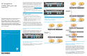
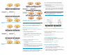

Figure 7 Point- to-point: 8-port (redundant, no single point
of failure)
Figure 8 Point-to-point : 4-port (redundant, no single point
of failure)
Figure 9 Point-to-point: 8-port to 4-port to 4-port
(redundant, no single point of failure)
Installing HP CWDM MUX modules
Refer to the HP StorageWorks CWDM MUX user guide for detailed
instructions on how to install the HP CWDM MUX modules.
Mounting the equipment in a rack
The HP CWDM 2-slot chassis can be mounted in a standard 19-inch
cabinet or rack.
To attach the chassis to a standard 19-inch rack:
1. Insert two cage nuts o n each rail.
2. Support the chassis so that all of the mounting holes in the HP
CWDM 2-slot chassis are aligned with the corresponding holes
in the rack.
3. Attach two rack-mounting screws to each side of the rack.
4. Tighten all of the screws in rotation.
Inserting a CWDM (SFP) transceiver
To insert a CWDM (SFP) transceiver:
1. Verify that the CWDM (SFP) transceiver is the correct model for
your application.
2. Grasp either side of the CWDM (SFP) transceiver with your thumb
and forefinger.
3. Insert the CWDM (SFP) transceiver into the slot on the front panel of
the FC or network device. You should hear a clicking sound when
you have properly seated the CWDM (SFP) transceiver.
Cabling HP CWDM MUX modules
Connecting fiber optic cables from the HP CWDM MUX module ports to
the CWDM (SFP) transceivers is simplified by color coding.
Figure 10 showshowtoconnectcablesfromtheCWDM(SFP)
transceiver to the equipment ports on a HP CW DM MUX module.
To connect fiber optic cables from the CWDM (SFP) transceiver to the
HP CWDM MUX module:
1. Clean all fiber optic connectors on the cable before inserting them
into the H P CWDM MUX module.
2. Connect one end of the fiber optic cable to the HP CWDM MUX
module connector, and connect the other end of the fiber optic
cable to the corresponding CWDM ( SFP) transceiver installed on
the FC or network device.
NOTE:
Consult your network planning diagram to map the fiber optic
cables to the CWDM (SFP) transceivers and equipment ports
on the HP CWDM MUX modules.
Figure 10 Cabling an HP CWDM Add/Drop MUX module
Connecting to the network
Therearetwopossiblenetworkconfigurations, using either two or three
HP CWDM M U X modules.
For non redundant cabling, see Figure 6.
For redundant cabling, see Figure 9.
Two HP CWDM MUX configuration
For a two HP CWDM MUX module configuration, connect the network
port of the first HP CWDM MUX module to the network port of the
second HP CWDM MUX module.
For non redundant cabling, see Figure 4 and Figure 5
For redundant cabling, see Figure 7 and Figure 8.
Three HP CWDM MUX configuration
For a three HP CWDM MUX module configuration:
1. Connect the network port of the HP CWDM 8-port
Multiplexer/Demultiplexer to the network port of the first HP CWDM
Slot A/Slot B 4-port Add/Drop Multip lexer.
2. Connect the pass port of the HP CWDM Slot A/Slot B 4-port
Add/Drop Multiplexer to the network port of the second HP CWDM
Slot B/Slot A 4-port Add/Drop Multip lexer.