
User Information and Service Guide - HP Carrier-Grade Server cc3310


HP cc3310 Carrier Grade Server Product Guide
Parts and Accessories
Chapter 10 115
6. Select Load SDRs only on to this server and Continue.
7. Set the date and time and select Continue.
8. Select Update just the SDR repository and Continue.
9. Select Yes – Activate BMC TAM and Continue.
10. Choose the desired LED configuration and select Continue.
11. Save the configuration to disk.
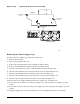
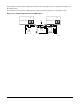
RJ-45 Serial Ports (Rear Panel)
The rear RJ-45 serial port is a fully functional serial port that supports any standard serial device and
provides support for serial concentrators. For server applications that use a serial concentrator to access the
server management features of the baseboard, a standard 8-pin CAT-5 cable from the serial concentrator is
plugged directly into the rear RJ-45 serial port. The 8 pins of the RJ-45 connector can be configured to match
either of two pinout standards used by serial port devices. To accommodate either standard, the J5A2
jumper block, located directly behind the rear RJ-45 serial port, must be jumpered appropriately according
to the desired standard. Pinouts are described in Table 12-2.
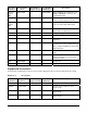
Table 12-2. Rear RJ-45 Connector Pinout
Pin Description Pin Description
1 RTS (Request to Send) 5 RIA (Ring Indicator)
2 DTR (Data Terminal ready) 6 RXD (Receive Data)
3 TXD (Transmit Data) 7 DSR/DCD (Date Set Ready/Data
Carrier Detect
4 GND (Signal ground) 8 CTS (Clear to Send)
RJ-45 Serial Port (Front Panel)
The front RJ-45 serial port is functionally identical to the rear panel port, but cannot be used at the same
time. The cable that attaches to the front panel port must include a jumper (short) between pins 4 and 5.
When this cable is connected, the rear panel connector is disabled. Pinouts are described in Table 12-3.
Table 12-3. Front RJ-45 Connector Pinout
Pin Description Pin Description
1 RTS (Request to Send) 5 GND (Ground disabled the rear
panel COM2 I/O port)
2 DTR (Data Terminal ready) 6 RXD (Receive Data)
3 TXD (Transmit Data) 7 DSR/DCD (Date Set Ready/Data
Carrier Detect
4 GND (Signal ground) 8 CTS (Clear to Send)
NOTE By default, the RJ-45 serial ports are configured to support a DSR signal.