
UserÆs Guide and Technical UserÆs Guide - HP Carrier Grade Server cc2300

94 cc2300 Carrier Grade Server Product Guide
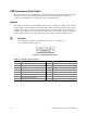
USB Connectors (Front Panel)
The server board provides two USB ports located behind the bezel. The built-in USB ports permit
the direct connection of two USB peripherals without an external hub. If more devices are
required, an external hub can be connected to either of the built-in ports.
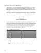
Alarms
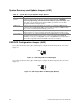
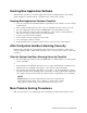
The alarms port interface is a standard DB15-pin connector (see Figure 28). This connector allows
remote display of alarm conditions. Each alarm (Major, Minor, Critical and Power) is the output of
a STDT relay contact. A common contact with normally open and normally closed connections is
included. Power alarm has just common and normally open contact outputs. The major and minor
alarms contain external reset circuits. Table 16 gives the pinout of the telco alarms connector.
CAUTION
Do not apply more than 60 Volts (maximum) to any pin or combination of
pins on the Telco Alarms connector.
18
915
Figure 28. 15-pin Alarms Connector
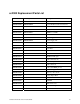
Table 16. Alarms Connector Pinout
Pin Description Pin Description
1 Minor reset, positive 9 Minor alarm, normally closed
2 Minor reset, negative 10 Minor alarm, common
3 Major reset, positive 11 Major alarm, normally open
4 Major reset, negative 12 Major alarm, normally closed
5 Critical alarm, normally open 13 Major alarm, common
6 Critical alarm, normally closed 14 Power alarm, normally open
7 Critical alarm, common 15 Power alarm, common
8 Minor alarm, normally open