
UserÆs Guide and Technical UserÆs Guide - HP Carrier Grade Server cc2300

cc2300 Carrier Grade Server Product Guide 93
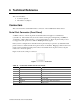
6 Technical Reference
This section includes:
• Connector pinouts
• Information on jumpers
Connectors
This section describes certain I/O interface connectors of the cc2300 Carrier Grade Server.
Serial Port Connector (Front Panel)
An RJ45 connector on the front panel located behind the bezel supplies a serial interface
(see Table 15). The interface may be used for either an emergency management port (EMP) for
“Crash Cart” or PC-to-PC connection, or as a normal serial port. The front panel serial port does
not support modem operation as it lacks an RI (Ring Indicate) signal.
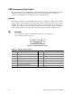
If the system is configured for both back and front panel serial port operation, by default the back
panel connector is enabled and the front panel connector is disabled. Plugging a cable into the front
panel connector disables the back panel connector and enables the front panel connector (if pins
4 and 5 are connected together).
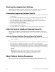
Figure 27 shows the serial port connector.
Figure 27. Serial Port Connector
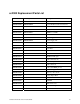
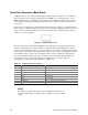
Table 15. Front Panel Serial Port Connector Pinout
Pin Signal Description
1 RTS Request to send
2 DTR Data terminal ready
3 TXD Transmit data
4 GND Ground
5 No Connection No Connection
6 RXD Receive data
7 DSR/DCD Date set ready / data carrier detect
1
8 CTS Clear to send
1
Use jumper on server board to select