
UserÆs Guide and Technical UserÆs Guide - HP Carrier Grade Server cc2300

cc2300 Carrier Grade Server Product Guide 79
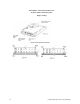
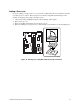
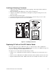
Installing or Removing a Terminator
1. Observe the safety and ESD precautions at the beginning of this chapter and the additional
cautions given here.
2. Raise the locking bar (B in Figure 23) on the socket (A in Figure 23).
3. Align the corner marks on the terminator (C in Figure 23) along the locking bar side of the
processor socket.
4. Place the terminator into the socket.
5. Lower the locking bar (D in Figure 23) until it latches to the side of the processor socket.
6. Perform these steps in reverse to remove the terminator.
OM11787
A
B
D
C
Figure 23. Installing a Terminator
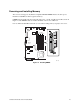
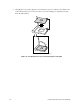
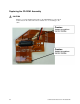
Replacing 3.3 Volt or 5 Volt PCI Add-in Cards
The server supports two types of PCI riser boards: 3.3 Volt and 5 Volt. The 5 Volt PCI riser
supports a full-length, full-height 64-bit 33 MHz PCI add-in card. The 3.3 Volt PCI riser supports a
low profile, half-length, 64-bit, 66 MHz PCI add-in card.
To replace a 3.3 V or 5.0 V add-in card, follow this procedure:
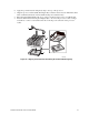
1. Lift the 3.3 V or 5.0 V PCI card retainer bracket up to unplug the riser board from the server
board.
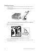
2. Insert or remove a PCI add-in card. Make sure that the add-in card fully seats in the riser card.
3. Replace the PCI retainer bracket. Make sure that the riser card fully seats in the server board.