
UserÆs Guide and Technical UserÆs Guide - HP Carrier Grade Server cc2300


cc2300 Carrier Grade Server Product Guide 67
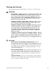
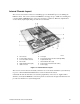
Internal Chassis Layout
The server board contains connectors for installing up to two Pentium III processors utilizing the
FCPGA sockets. The server board has six DIMM slots and supports up to 6 GB error checking and
correcting (ECC) SDRAM memory. The server board also contains two PCI slots (implemented
via riser cards), input/output (I/O) ports and various controllers.
A Server board G Serial port
B 5 V PCI add-in card riser H Front panel board (located beneath right HDD)
C 3.3 V PCI add-in card riser I Peripheral drive bay
D Fan module J SCSI hard disk drive (left)
E SCSI hard disk drive (right) K Power board (located beneath cables)
F USB connectors L Power supply
Figure 13. Internal Chassis Layout
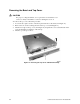
The server board is mounted horizontally toward the rear of the chassis behind the system fan array.
Up to two 1.0-inch SCSI Ultra160 hard drives can be mounted in the chassis.
Underneath the left side hard drive is located the peripheral bay. The server is supplied with a
slim-line (1/2-inch) CD-ROM drive. The front panel is located below the right side hard drive and
provides user interface for system management.