
UserÆs Guide and Technical UserÆs Guide - HP Carrier Grade Server cc2300

24 cc2300 Carrier Grade Server Product Guide
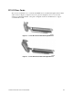
RJ45 Serial Port
The rear RJ45 serial port is a fully functional COM port that supports any standard serial device
and provides support for serial concentrators, which typically support RJ45 serial connectors. For
server applications that use a serial concentrator to access the server management features of the
baseboard, a standard 8-pin CAT-5 cable from the serial concentrator is plugged directly into the
rear RJ45 serial port. The 8 pins of the RJ45 connector can be configured to match either of two
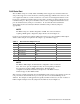
pin-out standards used by serial port concentrators. To accommodate either standard, the
J6A2 jumper block located directly behind the rear RJ45 serial port must be jumpered
appropriately.
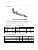
NOTE
The RJ45 serial port’s default configuration is DSR. For serial concentrators
requiring a DCD signal, configure the jumper block as shown in Figure 33.
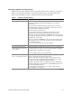
For those server applications requiring a DB9 serial connector, use an 8-pin RJ45-to-DB9 adapter.
Table 5 defines the pin-out required for the adapter to provide RS232 support.
Table 5. Rear Serial Port Adapter Pin-out
RJ45 Signal Abbreviation DB9
1 Request to Send RTS 7
2 Data Terminal Ready DTR 4
3 Transmitted Data TD 3
4 Signal Ground SGND 5
5 Ring Indicator RI 9
6 Received Data RD 2
7 DCD or DSR DCD/DSR 1 or 6
8 Clear To Send CTS 8
NOTE
The RJ45-to-DB9 adapter should match the configuration of the serial device
used. One of two pin-out configurations may be used depending on whether
the serial device requires a DSR or DCD signal. The final adapter
configuration should also match the desired pin-out of the RJ45 connector,
which can support either DSR or DCD.
This system is configured with both front and back RJ45 serial connectors, the adapters used for the
rear port cannot be used with the front port, as the pin-out for front and back RJ45 ports are
different. For example, modem applications typically use DCD. In this case, the user would use a
DCD-configured adapter and set the jumper block to DCD as shown in Figure 33.