
User Information and Service Guide - HP Carrier-Grade Server cc3310

96 Chapter 8
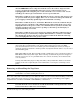
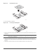
1. Push down on the blue locking button on the top cover while sliding the top cover rearward to release it
from the chassis.
2. Lift the top cover up to remove.
Figure 11-6. Removing the Top Cover
TP108
Internal Chassis Layout
The server uses the Telco and Industrial Grade server baseboard, which contains connectors for installing up
to two Intel
®
Xeon™ processors with 512 KB L2 cache utilizing the FCPGA sockets. The baseboard has
6 DIMM slots and supports up to 12 GB error checking and correcting (ECC) SDRAM memory. The Telco
and Industrial Grade server baseboard also contains 6 PCI slots (implemented via riser cards), input/output
(I/O) ports, and various controllers.
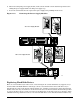
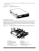
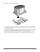
Figure 11-7. HP Carrier-Grade Server (shown with top cover and bezel removed)
TP124
D
M
L
K
J
I
H
G
F
E
C
B
A
A. Power supply H. Server fans
B. PCI card bracket (full-length) I. FPIO server board
C. Riser card assembly (full-length) J. RJ-45 COM2 and dual USB ports
D. PCI card bracket (low-profile) K. Control panel
E. Server baseboard L. SCSI hard disk drive bays
F. PCI add-in card (accessory to system)
G. Riser card assembly (low-profile)
M. Peripheral bay (optional CD-ROM module
or FDD module available)