
User Information and Service Guide - HP Carrier-Grade Server cc3310

Chapter 9 91
Bit I/O Name Description
LED, writing 1 turns both off. The relay and LED may also be turned on
by a FAN_FAIL_L signal.
1 O Critical alarm Writing 0 turns on the critical alarm relay and illuminates the
CRITICAL LED, writing 1 turns both off.
2 O Major alarm Writing a 1 to 0 edge will turn on the flip-flip that enables major alarm
relay. Writing a 1 will turn off the major alarm relay or a
MAJOR_RESET signal input. MAJOR LED is on when output is 0, off
when output is 1.
a
3 O Minor alarm Writing a 1 to 0 edge will turn on the flip-flip that enables major alarm
relay. Writing a 1 will turn off the major alarm relay or a
MINOR_RESET signal input. MINOR LED is on when output is 0, off
when output is 1.
a
4 I Major alarm
sense
Senses the state of the major alarm relay. 0 relay is on, 1 relay is off.
This allows software to detect if the MAJOR_RESET signal was
activated. Always write 1 during write operations.
5 I Minor alarm
sense
Senses the state of the minor alarm relay. 0 relay is on, 1 relay is off.
This allows software to detect if the MINOR_RESET signal was
activated. Always write 1 during write operations.
6 I Critical/major
color
Writing a 1 turns CRITICL and MAJOR LEDs to yellow, 0 color is red.
Strapping J7D1 pins forces LEDs to red. Resets to yellow.
a. Normally closed (NC) and normally open (NO) relay contacts are provided on the rear panel Telco alarms
connector. To activate the relay, a 1 to 0 transition must be written.
Replacing Power Supply Modules
To maintain hot-plug capability, ensure that an active AC or DC power supply module is in the adjacent slot
before replacing a power supply module.
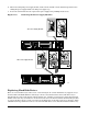
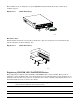
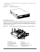
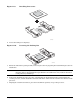
To replace an AC power supply module, follow this procedure:
1. Press in locking tab inside of green handle (A in Figure 11-2).
2. Pull green handle slightly downward and rearward, sliding the AC power supply module out of the AC
power supply cage (B and C in Figure 11-2).
3. When reinserting an AC power supply module, make sure the green handle is in the downward position
before sliding AC power supply module into AC power supply cage.
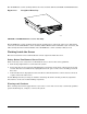
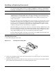
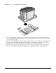
To replace a DC power supply module, follow this procedure:
1. Disconnect the power cord/cable from the DC source. (Remove power from the power supply.)
2. Using a small flat-head screwdriver, unlatch the black connector cover from the connector base and flip
connector cover up (D in Figure 11-2).
3. Disconnect DC power plug from power supply module by pulling DC power plug rearward (E in Figure
11-2). Flip black connector cover down and relatch connector cover to connector base.
4. Using a Phillips screwdriver, remove the two screws that secure the terminal block to the DC power
supply module.
5. Press in green button on handle and pull handle downward. At the same time, pull DC power supply
module out of DC power supply cage (F, G, and H in Figure 11-2).