
User Information and Service Guide - HP Carrier-Grade Server cc3310


32 Chapter 3
Interface Requirements
DC Input
The DC power source may produce hazardous voltage levels exceeding –60 VDC and high energy levels
above 240 VAC that may cause electric shock. All DC input connections should be made only by a qualified
service person to prevent injury. All wiring terminals connected to the DC input terminal block must be fully
insulated with no exposed bare metal.
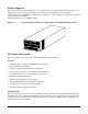
DC Output Connectors
The power subsystem DC power and control signals are interfaced to the server via wire harnesses when the
power supply modules are inserted into the power subsystem enclosure. The safety ground pin of the power
supply module is the first pin to connect and the last to disconnect when the module is being inserted or
removed from the power subsystem housing. In addition to the 5-V Standby, –12V, +3.3V, +5V and +12 VDC
outputs, the following signals and output pins are included:
• +3.3 VDC remote sense
• +5 VDC remote sense
• +12 VDC remote sense
• Remote sense return
• Power subsystem on (DC PWR enable)
• Power good
• I
2
C interface chip (PS Failure, PS Presence, PS Predictive Fail, +12V Mon, +5V Mon, and the 5V
Standby rails failure are being monitored via an I
2
C interface chip)
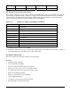
Power Supply Module LED Indicators
There is a single bi-color LED to indicate power supply status that is visible on the back of the server. Table
3-2 shows the conditions confirmed by the LED indicators.
Table 3-2. LED Indicators
Power Supply Condition Power Supply LED
No DC power to all PSUs OFF
No DC power to this PSU only AMBER
DC present/only standby outputs on BLINK GREEN
Power supply DC outputs on and ok GREEN
Current limit AMBER
Power supply failure (OTP, OCP, OVP, UV) AMBER
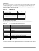
DC Input Voltage Specification
The power supply will operate within all specified limits over the input voltage range outlined in Table 3-3.
The power supply will power-off if the DC input is less than –34 VDC.
Table 3-3. DC Input Rating
Minimum Nominal Maximum Maximum