
User Information and Service Guide - HP Carrier-Grade Server cc3310

Chapter 2 25
The 82546EB controller supports the following features:
• 32-bit PCI master interface
• Integrated IEEE 802.3 10Base-T, 100Base-TX and 1000Base-TX compatible PHY
• IEEE 820.3u auto-negotiation support
• Full-duplex support at 10 Mbps, 100 Mbps, and 1000 Mbps operation
• Low power +3.3V device
On the server board, NIC 1 can be used as both a network interface and server management interface.
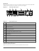
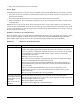
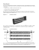
NIC Connector and Status LEDs
The E82546EB controller drives LEDs on the network interface connector that indicate link/activity on the
LAN and speed of operation. The green LED indicates network connection when on and TX/RX activity when
blinking. The speed LED indicates 1000 Mbps when amber, 100 Mbps when green, and 10 Mbps when off.
Keyboard and Mouse
The keyboard/mouse controller is PS/2-compatible. If specified through the system setup utility, the server
may be locked automatically if there is no keyboard or mouse activity for a predefined length of time. Once
the inactivity (lockout) timer has expired, the keyboard and mouse do not respond until the previously stored
password is entered. A Y-cable can be used if both a PS/2 mouse and keyboard are required at the same
time.
RJ-45 Serial Port (Rear Panel)
The rear RJ-45 serial port is a fully functional serial port that supports any standard serial device and
provides support for serial concentrators. For server applications that use a serial concentrator to access the
server management features of the baseboard, a standard 8-pin CAT-5 cable from the serial concentrator is
plugged directly into the rear RJ-45 serial port. The 8 pins of the RJ-45 connector can be configured to match
either of two pin-out standards used by serial port devices. To accommodate either standard, the J5A2
jumper block located directly behind the rear RJ-45 serial port must be jumpered appropriately according to
the desired standard.
RJ-45 Serial Port (Front Panel)
The front RJ-45 serial port is functionally identical to the rear panel port, but cannot be used at the same
time. The cable that attaches to the front panel port must include a jumper (short) between pins 4 and 5.
When this cable is connected, the rear panel connector is disabled.
NOTE By default, the RJ-45 serial ports are configured to support a DSR signal.
ACPI
The server board supports the Advanced Configuration and Power Interface (ACPI) as defined by the ACPI
2.0 specification. An ACPI-aware operating system can put the server into a state where the hard drives spin
down, the server fans stop, and all processing is halted. However, the power supply will still be on and the
processors will still be dissipating some power, so the power supply fans will still run.
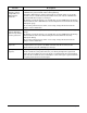
The server board supports sleep states s0, s1, s4, and s5:
• s0: Normal running state.
• s1: Processor sleep state. No context will be lost in this state and the processor caches will maintain
coherency.