
User Information and Service Guide - HP Carrier-Grade Server cc3310

88 Chapter 8
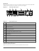
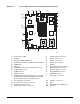
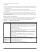
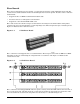
Figure 2-5. Server Board Connector and Component Locations
OM14124
F
G
A CE
B
LN MOS R Q
PT
I
H
K
J
Y
U
V
W
AA
Z
BB
X
CC
D
DD
A. System status LED P. Auxiliary signal connector
B. ID LED Q. Sys fan 1 connector
C. Diagnostic LEDs (POST code) R. Sys fan 2 connector
D. 64-bit PCI riser slot for PCI-X bus B (full height) S. Main power connector
E. DIMM slots T. Battery
F. I/O ports U. Power supply signal connector
G. SCSI channel B connector (SCSI version only) V. ATX front panel connector
H. COM 1 serial header W. SSI front panel connector
I. ICMB connector X. Floppy/FP/IDE connector
J. IPMB connector Y. ATA/IDE connector
K.
64-bit PCI riser slot for PCI-X bus C (low profile)
RADIOS enabled. Modular ROM-B card support
is provided via the riser card (SCSI only)
Z. Floppy drive connector
L. Secondary processor socket AA. USB 2 & 3 connector
M. Secondary processor fan connector BB. N/A
N. Primary processor socket CC. Hard disk drive LED header
O. Primary processor fan connector DD. Speaker