
User Information and Service Guide - HP Carrier-Grade Server cc3310

Chapter 8 89
Back Panel
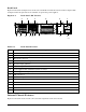
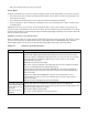
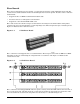
Figure 2-4 shows the back panel view of the server and Table 2-4 lists the features of the back panel. The
back panel of the AC-powered server is similar (except for the power supplies).
Figure 2-4. Back Panel (DC Version)
TP250
A B C D E F
O N M L K J I H G
Table 2-4. Back Panel Features
Item Description
A PCI card bracket (low profile)
B RJ-45 NIC2 connector – green status LED / yellow status LED
C DB15 alarm connector
D PCI card bracket (full-height)
E DC power input (primary)
F DC power input (redundant)
G Power supply module, redundant (system accessory)
H Power supply module, primary
I USB connector 2
J RJ-45 serial 2 port
K PS/2 mouse/keyboard connector – requires dongle (Y cable) to connect both keyboard and mouse
L RJ-45 NIC1 connector
M U-320 SCSI connector
N Video connector
O USB connector 1
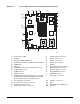
Internal Chassis Features
Figure 2-5 shows the location of the connectors and components on the server board.