
User Information and Service Guide - HP Carrier-Grade Server cc3310


Chapter 8 89
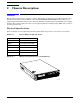
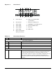
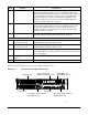
Figure 2-2. Front Panel
A B CDEF
GHIJKLM
A Power switch H Disk 2 activity/fault LED
(green/amber)
B Reset Switch I Main power LED (green)
C Alarm: CRT J NIC0/NIC1 activity LED (green)
D Alarm: MJR K System ID LED (white)
E Alarm: MNR L ID switch
F Alarm: PWR M NMI switch
G Disk 1 activity/fault
LED (green/amber)
Table 2-3. Front Panel Features
Item Feature Description
Front Panel Switches
A Power switch Toggles the server power.
B Reset switch Resets the server.
L ID switch Toggles server ID LED.
M NMI switch Assert NMI to baseboard.
Front Panel Alarm LEDs and Relays
C Critical (amber or red) When continuously lit, indicates the presence of a critical system
fault. A critical system fault is an error or event that is detected by
the system with a fatal impact to the system. In this case, the
system cannot continue to operate. An example could be the loss of a
large section of memory, or other corruption, that renders the
system not operational. The front panel critical alarm relay will be
engaged.