
User Information and Service Guide - HP Carrier-Grade Server cc3310


Chapter 9 111
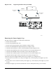
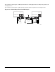
Figure 11-19. Replacing the Fan Array Assembly
TP132
Fan Array Assembly
Fan Guard
Blue Captive
Screw
Blue Captive
Screw
Blue Captive
Screw
Removing the Power Supply Cage
To replace the power supply cage, follow these instructions:
1. Remove the front bezel.
2. Remove the peripheral drive tray.
3. Remove the fan guard and fan array assembly (see Figure 11-19).
4. Remove the full-length PCI adapter subsystem (see Figure 11-16).
5. Disconnect the PS/2 power connector from the FPIO board (F in Figure 11-18).
6. Disconnect the SSI front panel connector from the server board (W in Figure 2-5).
7. Disconnect the ID LED connector form the server board (B in Figure 2-5).
8. Disconnect the auxiliary signal connector from the server board (P in Figure 2-5).
9. Disconnect the PS signal connector from the server board (U in Figure 2-5).
10. Remove the power supply modules from the power supply cage (see Figure 11-2).
11. Loosen the 2 screws at the rear of the power supply cage, connecting the power supply cage to the
chassis.
12. Loosen the one screw at the front of the power supply cage, connecting the power supply cage to the
chassis.
13. Pull power supply cage forward (towards front of server) and upward. Lift cage out of chassis.