
User Information and Service Guide - HP Carrier-Grade Server cc3310

108 Chapter 8
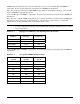
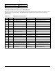
Table 11-5. Segment B PCI Bus Maximum Speed Table
Number of Slots Populated Bus Speed
Empty riser 100 MHz PCI-X
1 Slot (bottom) 100 MHz PCI-X
2 Slots (bottom and middle) 66 MHz PCI-X
3 Slots 66 MHz PCI-X
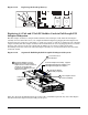
Replacing 3.3-Volt and 5-Volt Add-in Cards in Low Profile, Half-
Length PCI Adapter Subsystem
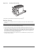
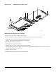
A three-slot PCI adapter assembly that supports only low-profile, half-length PCI adapters is installed in the
Segment C PCI riser slot located on the right side of the server baseboard. This PCI adapter assembly is
configured and installed as shown in Figure 11-17. After the PCI adapter assembly is removed from the
server, it is configured with PCI adapters by plugging the PCI adapters into the PCI connectors on the 3.3-
Volt riser card that is part of the PCI adapter assembly. The PCI adapter assembly is then installed into the
server by plugging the riser card into the riser card connector on the server baseboard. In addition, it is
necessary to make sure that the interlocking metal tabs on the back of the PCI adapter assembly are
correctly inserted into the slots in the back of the chassis.
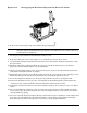
Figure 11-17. Segment C Low-Profile, Half-Length PCI Adapter Subsystem
TP129
Install PCI Adapters in PCI
Adapter Assembly
1
2
Low-Profile, Half-Length
PCI Adapter
3-slot PCI Adapter Assembly - supports
only low-profile/half-length PCI adapters
Install PCI Adapter
Assembly in System
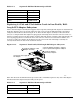
Table 11-6 shows the maximum PCI bus speed achievable on PCI Bus Segment C. Any slower PCI adapter
installed in the PCI adapter subsystem will gate the speed.
Table 11-6. Segment C PCI Bus Maximum Speed Table
Number of Slots Populated Bus Speed
Empty Riser 100 MHz PCI-X
1 Slot (bottom) 100 MHz PCI-X