
- HP All-in-One Printer Manual

Q2431-90912 Chapter 5 Theory of operation 77
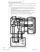
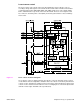
Laser/scanner control
The laser/scanner control circuit on the laser driver PCA turns the laser diodes on an off
according to image data signals received from the DC controller PCA. The DC controller PCA
sends image data signals VD01/VD01,VD02, and /VD02 and the laser control signals CNT0,
CNT1, and CNT2 to the logic circuit on the laser driver PCA. The laser control signals control
laser emission, automatic power control (APC), horizontal synchronization control, and image
mask control.
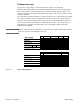
Figure 13. Laser control circuit block diagram
Laser emission control is simply turning the laser diodes on and off. Automatic power control is
used to limit the amount of light that is emitted from the laser diodes. Horizontal synchronization
control is used to determine the starting position for the images horizontal direction. Image mask
control is used to avoid laser beam emission on the non-imaging areas of the drum (about 5mm
down the vertical edges and 8mm at the top and bottom)