
- HP All-in-One Printer Manual


Q2431-90912 Chapter 6 Removing and replacing parts 193
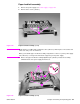
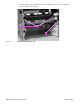
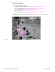
3. Remove three screws (callout 3). Depress the pickup-gear-cover upper retainer tab
(callout 4) to release it. Lift up on the cover to release the lower retaining tab (not shown) and
remove the cover.
Figure 147. Tray 1 pickup assembly (2 of 4)
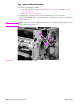
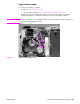
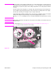
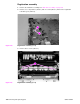
4. Unplug the pickup sensor connector (callout 5). Remove six screws (callout 6).
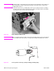
Reinstall note One of the screws (callout 7) on the left side is longer that the others. Make sure that this screw
is replaced in the same hole it is removed from.
Figure 148. Tray 1 pickup assembly (3 of 4)
3
4
4
3
4
7
6
5
6
5
6
6
7