
- HP All-in-One Printer Manual


192 Removing and replacing parts Q2431-90912
Tray 1 paper-pickup assembly
1. Remove the following assemblies:
● Top, right-side, and left-side covers. See “Top cover” on page 146 through “Left-side
cover” on page 151.
● Tray 1. See “Tray 1” on page 152.
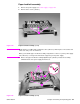
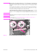
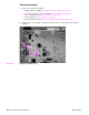
2. Unplug the tray 1 pickup solenoid connector and the top-cover sensor from the
DC controller PCA (locations J79 and J95; callout 1). Unweave the harnesses from the wire
guide (callout 2).
Hint It might be necessary to remove additional wire-harnesses from the wire guide to gain access to
the solenoid and sensor harnesses.
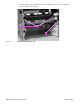
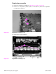
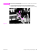
Figure 146. Tray 1 pickup assembly (1 of 4)
2
1
2
1