
- HP All-in-One Printer Manual

Q2431-90912 Chapter 6 Removing and replacing parts 181
DC controller PCA
1. Remove the following assemblies:
● Top and right-side covers. See “Top cover” on page 146 and “Right-side cover” on
page 149.
● Formatter assembly. See “Formatter assembly” on page 161.
CAUTION The product contains components that are sensitive to electrostatic discharge (ESD). Always
perform service work at an ESD-protected workstation. If an ESD-protected workstation is not
available, discharge body static by grasping the printer chassis before touching an
ESD-sensitive component. Ground the printer chassis before servicing the product.
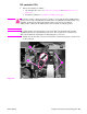
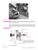
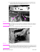
CAUTION The yellow and blue heavy-gauge wires connected to DC controller PCA locations TB85
and TB86 (callout 3) are not terminal lug connectors. These terminals are soldered to the
DC controller PCA. Do not attempt to forcibly unplug these connectors.
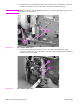
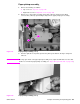
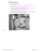
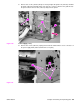
2. Unplug all of the wire/cable connectors from the DC controller PCA (callout 1). Remove two
screws (callout 2).
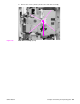
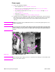
Figure 128. DC controller PCA (1 of 3)
1
2
4
1
2
3