
- HP All-in-One Printer Manual

Q2431-90912 Chapter 6 Removing and replacing parts 135
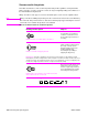
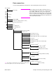
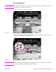
Parts-removal tree
Use the following diagram to determine the order in which parts must be removed.
Print cartridge
Note Some components in the parts-removal tree have a
superscript number listed next to the component name
(for example, “Right-side cover
1
”). The superscript
indicates that this component must be removed to gain
access to the transfer assembly and to the registration
roller assembly. Components with superscript letters are
removed in numerical order.
Transfer roller
Control-panel overlay
Tray 1
Tray 2 feed rollers
Rear output bin
Formatter cover
Firmware DIMM
Formatter assembly (2 machine screws)
Accessory covers and the tray 2 extension door
Fuser
Tray 1 pickup roller
Tray 1 separation pad
Top cover
Control-panel assembly
Right-side cover
1
Tray 2 media-size sensor
Tray 2 lifter-drive assembly
Cooling fan (right side; HP LaserJet 4300 only)
2
Laser/scanner
Paper-pickup assembly
3
Print-cartridge motor (HP LaserJet 4300 only)
4
Main motor
DC controller assembly
5
Main drive assembly
6
Components listed with superscripts
1, 2, 5, 6
Left-side cover
7
Registration-roller assembly
Output delivery assembly
8
Duplexing pendulum assembly
Main cooling fan (left side)
Power supply
9
Paper-feed assembly
Tray 1 pickup assembly
10
Components listed with superscripts
1, 3, 4, 5, 6, 7, 8, 9, 10
Note: The formatter assembly and fuser are only listed once, but they must
be removed to gain access to some of the other components.
Transfer assembly