HP Designjet T1100/T1100ps/T610/ T1120/T1120ps Printer Series Version 6 March 19, 2009
For HP Internal Use Only Warranty WARNING ©Copyright Hewlett-Packard Company 2009 The information contained in this document is subject to change without notice. The procedures described in this manual are to be performed by HP-qualified service personnel only. This document contains proprietary information that is protected by copyright. All rights are reserved.
Table of Contents 1 2 3 4 5 6 7 1 Troubleshooting System Error Codes Service Tests and Utilities Service Calibrations Parts and Diagrams Removal and Installation Preventive Maintenance For information about Using this Manual, please refer to the next page.
Table of Contents Using this Manual Purpose This Service Manual contains information necessary to test, calibrate and service: HP designjet T1100 Printer 24 inch (Model Q6683A) HP designjet T1100 Printer 44 inch (Model Q6687A) HP designjet T1100ps Printer 24 inch (Model Q6684A) HP designjet T1100ps Printer 44 inch (Model Q6688A) HP designjet T610 Printer 24 inch (Model Q6711A) HP designjet T610 Printer 44 inch (Model Q6712A) HP designjet T1120 Printer 24 inch (Model CK837A) HP designjet T11
Troubleshooting 1 Using the Front Panel 1-3 1 General Troubleshooting 1-4 Introduction 1-4 Troubleshooting System Error Codes 1-4 Performing a Service Test on a failed Assembly 1-4 Performing the Necessary Service Calibrations 1-4 The Front Panel is blank 1-5 Solving Print Quality Problems 1-5 The Printer does not Power ON 1-5 The Printer Continuously Rejects Printheads 1-5 Cover Sensors are not Working 1-5 The Line Sensor has Problems Detecting Media 1-5 Banding at variable extreme environmental condit
Problems with Color Accuracy 1-33 Output Only Contains a Partial Print 1-34 Problems with Image Clipping 1-34 Some objects are missing from the printed image 1-35 A PDF file is clipped or objects are missing 1-35 Print Quality Troubleshooting Wizard 1-35 Ink Supplies Troubleshooting 1-39 Introduction to ink supplies 1-39 What are Ink Supplies? 1-39 Ink Cartridges 1-39 Available Ink Cartridges 1-40 Printheads 1-40 Available Printheads 1-41 General Information About the Ink Supplies 1-41 General Precautions W
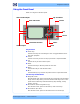
Using the Front Panel Using the Front Panel Below is a diagram of the front panel. View Loaded Paper Up and Down View Ink Levels Cancel OK Power Form Feed and Cut Unload Paper Menu Back Key Function Arrow Keys Use the Arrow keys to scroll through a menu or toggle between YES or NO when prompted. Cancel Use the Cancel key to abort or stop a procedure or reject test results. OK Use the OK key to select a menu option. Power Use the Power key to turn the printer ON and OFF.
Troubleshooting General Troubleshooting Introduction This chapter will guide you through the relevant steps to take when troubleshooting the printer. Troubleshooting System Error Codes Chapter 2 System Error Codes on page 2-1 contains a list of system error codes and their respective descriptions and recommended corrective actions. Only try one recommended action at a time and check if the error code has disappeared.
General Troubleshooting Solving Print Quality Problems Whenever a Print Quality problem appears, it is advisable to print the Diagnostic Print to help diagnose the problem. The Diagnostic Print will help you differentiate between possible printhead errors and other problems such as incorrect front-panel selection, driver or RIP configuration or mechanical problems. The Front Panel is blank 1 See What to do if the Front Panel is blank on page 2-3.
Troubleshooting Troubleshooting Media Jams/Printhead Crashes The failure modes "media jam" and "head crash" are grouped together because in many cases a media jam causes the media to lift up into the Carriage path and cause a Printhead crash, thus causing many media jam failures to be reported as head crashes. 1 Did the media jam occur when loading media? If the client has had media jams, it is common for pieces of media to get stuck in the media path. Clear the media path.
The Media Basket was damaged during printer setup The Media Basket was damaged during printer setup 1 There are three plastic parts that could break during printer installation and need replacing. 2 Check the parts table and graphics in Parts and Diagrams to identify what service parts you must order. See Printer Support on page 5-2. 3 Replace the component. See Bin Assembly on page 6-10.
The Media Basket was damaged during printer setup Spindle Holder (rewinder included) is misaligned or not properly attached to the printer, the Rewinder will not function properly. To further diagnose problems with the Rewinder, See 6. Rewinder on page 3-34.
Print quality troubleshooting Print quality troubleshooting Print Quality Troubleshooting Actions For some Print Quality problems, a Call Agent can try and troubleshoot the Printer by requesting the Customer to perform certain actions. Using this process, most problems can resolved without the need of an on-site visit. Use the Print Quality Troubleshooting Wizard to help customers with their print quality or color problems.
Print quality troubleshooting The Image Quality Service Best Plot uses the Best Print Mode and is divided in to three parts as follows: Diagnostic Part 1: Printhead Reliability Test. The purpose of this test is to identify which Printhead is faulty. Diagnostic Part 2: Printhead Alignment Test. This test is designed to check any color-to-color and bi-directional misalignment the printer may have. Diagnostic Part 3: Printheads and Paper Advance test.
Print quality troubleshooting Alignment Diagnostic, Nozzle Health, Force Drop Detection or Print Banding Plot, and press the Enter key to start printing. 4 Make sure media is loaded, the Media Lever is lowered and that the Ink System is correctly installed. Press the OK key to print the Diagnostic Print or press Back/Cancel to exit without printing the Diagnostic Print. 5 The selected Diagnostic Print will now be printed.
Print quality troubleshooting Below, the stepped lines highlighted in yellow are broken. When the line is completely broken, this means the nozzle is out. Below, the stepped lines highlighted in yellow are misdirected. When the line is misdirected, this means the nozzle is malfunctioning or out of position. On the left of each Printhead Nozzle test, there is a series of horizontal straight lines. If one or more nozzles are misdirected there will be unequal spaces between the corresponding lines.
Print quality troubleshooting 1 If the Printer is experiencing horizontal misalignment problems, the Alignment Test will show something like this: 2 If the Printer is experiencing vertical misalignment problems, the Alignment Test will show something like this: 3 If the Printer is experiencing bi-directional misalignment problems, the Alignment Test will show something like this: Corrective Action Perform the Printhead Alignment (Main Menu/Image Quality Maintenance/ Align Printheads), using the same pape
Print quality troubleshooting Banding If the Printer is experiencing a banding problem, you will see repetitive horizontal bands within the printed image. Darker horizontal bands or lines repeated along the vertical band (from top to bottom at the same distance). Whiter horizontal bands or lines along the vertical band (from top to bottom at the same distance). The plot is printed in Best or Normal mode (according to the menu option selected) with Error Hiding ON.
Print quality troubleshooting In high quality modes, graininess in ALL colors can indicate problems either with alignment or Paper Advance. Corrective Action In order to solve problems that result in banding, try the following: 1 Check that the appropriate print quality settings are being used (refer to the User’s Guide for more information). 2 Check that the loaded media is the same type as selected in the printer.
Print quality troubleshooting Printing the Advanced Diagnostics Print 1 In the Service Utilities submenu, scroll to “Diagnostic Print” and press OK. 2 You will be given three options. Use the Arrow keys to select the Advanced Diagnostics menu. 3 From the displayed options, use the Arrow keys to make the required selection Paper Advance, Printhead Alignment Diagnostic, Nozzle Health, Force Drop Detection or Print Banding Plot, and press the OK key to start printing.
Print quality troubleshooting The whitest vertical line should be positioned in the 0 offset column with minor variations between +2 and -2 columns. If the offset is not positioned on the 0 column or between +2 and -2 columns and the whitest vertical varies greatly, the printer requires Paper Advance Calibration (Main Menu/ Image Quality Maintenance/Paper Advance Calibration/Calibrate Paper Advance). It is very important to verify that the loaded media is the same media type as selected in the front panel.
Print quality troubleshooting The following plot shows correct media advance, there is a straight white line positioned close to the 0 column for the majority of the points.
Print quality troubleshooting The following plot shows a bad media advance, there is a straight white line positioned close to the -6 column, instead of the 0 column for the majority of the points. Corrective Action To fix Paper Advance problems, try the following: 1 Check the Paper Advance Calibration Status. This can be done by going to Main Menu/Paper/View Loaded Paper. At the bottom, the Front Panel displays the Paper Advance Calibration status. There are three status messages: DEFAULT.
Print quality troubleshooting 2 To calibrate the Paper Advance from the user menu, go to Main Menu/ Image Quality Maintenance/Paper Advance Calibration/Calibrate Paper Advance. It is very important to verify that the loaded media is the same media type as selected in the front panel. You can verify the media type selected through the Front Panel (Main Menu/Paper menu/View loaded paper). The wrong type of paper selected will produce an offset error in the Paper Advance.
Print quality troubleshooting The illustration shows the complete Printhead Alignment that identifies each of the specific alignment test results covered.
Print quality troubleshooting The results are seperated onto two screens. Use the Arrow keys to display the second results screen. Any printhead with a test result containing a number that is not within the ±3 dot row range is misaligned. The mK printhead is used as a reference to test the other printheads. If all the printheads fail the Pen to Pen tests, it is the mK printhead that is misaligned.
Print quality troubleshooting If the customer is using non-HP media and after the Image Quality Test you still have the same image quality problems, change to genuine HP media and repeat the Image Quality Test. The best alignment calibration is obtained using HP Photo Paper. Nozzle Health The print contains three separate parts. a b c a The Variable Frequency Nozzle health plot with odd/even nozzles separation.
Print quality troubleshooting 2 Reprint the Nozzle Print test to check that the defective nozzles have been corrected. 3 If the problem continues, replace the defective Printhead. Force Drop Detection If the Nozzle Print Test plot has persistent white point banding in only one color that cannot be fixed with a printhead recovery, you can use this option to resolve the problem by resetting the nozzle health data base so that all nozzles are assumed to be correct.
Print quality troubleshooting Horizontal Lines Across the Image (Banding) Description of problem When you look at the image you have printed, there are horizontal lines across the image. Shown below is an example of what you might see if you have this problem: Corrective Action 1 Check that the paper type loaded corresponds to the paper type selected in the front panel and in the software. You can verify the paper type selected through the Front Panel (Main Menu/Paper menu/View loaded paper).
Print quality troubleshooting If printing over a LAN, it is possible that the LAN is too slow to meet the requirements of the print job. If this is the case, the following corrective measures can be taken: 1 Do not use the computer while printing. Close applications that use a large amount of computer resources. 2 Convert the file PDF. Formats like PDF require less resources to print, which may solve your banding problem.
Print quality troubleshooting Problems with Stepped Lines Description of problem When you look at the image you have printed there are ‘stepped lines’ in the borders of arrows and diagonal lines. The lines should be straight with no stepping. Shown below is an example of what you might see if you have problems with Stepped Lines: Corrective Action 1 The problems may be inherent in the image that you are trying to print. Try to improve the image with the application that generated the file.
Print quality troubleshooting Corrective Action 1 Reseat the Printheads by removing them and then reinserting them. As you reseat the printheads, the printer will automatically align the printheads. It is important that the alignment is completed properly. See Aligning Printheads on page 3-14. Lines are discontinuous If the lines are broken in the following way: 1 Check that the appropriate print quality settings are being used (refer to the User’s Guide for more information).
Print quality troubleshooting 3 Try using a heavier paper type. When printing dense colors, it is recommended to use HP Heavyweight Coated Paper or HP Super Heavyweight Coated Paper. 4 If glossy paper is being used, try changing to a different type of glossy paper. 5 Align the printheads. See Image Quality Maintenance Procedure on page 1-49.
Print quality troubleshooting Shown below is an example of what you might see if you have problems with the paper not being flat: Corrective Action 1 Check that the paper type loaded corresponds to the paper type selected in the front panel and in the software. You can verify the paper type selected through the Front Panel (Main Menu/Paper menu/View loaded paper). 2 Try using a heavier paper type.
Print quality troubleshooting Horizontal smears on the front of coated paper If a lot of ink is used on plain or coated paper, the paper absorbs the ink quickly and expands. As the printheads move over the paper, the printheads may come into contact with the paper and smear the printed image. This problem is normally seen only on cut sheets of paper (not on roll paper). Corrective Action 1 Check that the paper type loaded corresponds to the paper type selected in the front panel and in the software.
Print quality troubleshooting Problems with the Edges of objects Stepped or not sharp The edges of objects or lines appear to be poorly defined or lighter in density than expected. Corrective Action If the print quality slider has already been set to Quality in the Print dialog, select the custom print quality options, and try setting the quality level to Normal (refer to the User’s Guide for more information). Darker than expected The edges of objects seem darker than expected.
Print quality troubleshooting Corrective Action 1 Try using a heavier paper type. When printing dense colors, it is recommended to use HP Heavyweight Coated Paper or HP Super Heavyweight Coated Paper. 2 Use higher print quality settings (refer to the User’s Guide for more information). White spots on the print White spots are seen on the print. This is probably due to paper fibers, dust, or loose coating material.
Print quality troubleshooting 6 Print the Service Image Diagnostics Print, and clean any printheads that need cleaning. Reprint the job in case the problem has been solved. Color accuracy using EPS or PDF images in page layout applications Page layout applications such as Adobe InDesign and QuarkXPress do not support color management of EPS, PDF, or grayscale files.
Print quality troubleshooting If necessary, change the printable area in the software. If necessary, reduce the size of the image or document in your software application, so it fits between the margins Another Possible Explanation Some applications, such as Adobe Photoshop, Adobe Illustrator, and CorelDRAW, use an internal 16–bit coordinate system which means that they cannot handle an image of more than 32,768 pixels.
Print quality troubleshooting Some of these corrective actions that the customer can perform to enhance the print and/or color quality are: printhead cleaning, media advance calibration, printhead alignment, and color calibration. The main benefits of this Print Quality Troubleshooting Wizard tool are that it creates a better customer experience, solving customer PQ issues fast, efficiently, and with a minimum cost for them and also for HP Support.
Print quality troubleshooting Troubleshooting color issues such as: – Colors are inaccurate Troubleshooting printhead reliability issues Corrective actions a customer can perform: The corrective actions on the printer’s systems that the customer can perform to enhanced the print and/or color quality are: Clean Printheads is recommended only if the customer is experiencing problems with print quality where we know that printhead cleaning will help.
Print quality troubleshooting select Print quality troubleshooting. 2 From the Embedded Web Server: go to the Support tab, then select Print quality troubleshooting. For Mac OS 1 From the HP Printer Utility under Mac OS: select Support, and then Print quality troubleshooting. 2 From the Mac OS Print dialog: go to the Services panel, select Device Maintenance, then select Print quality troubleshooting from the list of maintenance tasks.
Ink Supplies Troubleshooting Ink Supplies Troubleshooting Introduction to ink supplies What are Ink Supplies? For each of the ink colors used in the printer, there are two components, the Printhead and Ink Cartridge. These components are called Ink Supplies. Ink Cartridges Printheads Ink Cartridges The printer's six Ink Cartridges provide matte black, magenta, yeloow, cyan, gray and photo black ink to the Printheads.
Ink Supplies Troubleshooting The front panel displays the status of the Ink Cartridge. Using the front panel, detailed information can be checked on the Ink Cartridges.
Ink Supplies Troubleshooting Available Printheads Printhead Type Printer Model C9380A HP 72 Gray & Photo Black Printhead HP 72 Magenta & Cyan Printhead Part number All HP 72 Matte Black & Yellow Printhead C9383A C9384A General Information About the Ink Supplies For optimum results from the printer and modular ink delivery system always follow these guidelines when handling the ink supplies: Always install the Ink Cartridges and Printheads before the expiration date, which is on the packaging.
Ink Supplies Troubleshooting When Should You Replace the Ink Supplies? When to change the ink supplies is mostly determined by you with guidance from the front panel. In conjunction with the messages displayed in the front panel and the message explanations in this chapter, you will be able to choose for yourself when is the right time to change the ink supplies. The Printer will also display the ink level and will tell you when the ink supply is low on ink.
Ink Supplies Troubleshooting 2 In the Ink Menu submenu, scroll to Ink cartridge information and press OK. 3 In the Ink Cartridge Information submenu, scroll to the Ink Cartridge that you want information on and press OK. 4 The front panel displays information on the selected Ink Cartridge. Use the Arrow keys to scroll through the information. The information supplied is: The color of the Ink Cartridge The make of the Ink Cartridge (hp no.72 is recommended).
Ink Supplies Troubleshooting The printer consumes more gray ink ink than M, C, or Y This is not a problem, and no action should be taken to “correct” this attribute of the printer. In general the higher frequency of change is because Matte Black ink is the one that is used for lines and black objects in technical papers (bond, coated, HW coated, natural tracing paper, etc.), which are the types of contents that are more commonly printed with this type of printer.
Ink Supplies Troubleshooting 1 Scroll to the Ink Menu icon and press OK. 2 In the Ink Menu submenu, scroll to Replace ink cartridges and press OK. 3 The front panel displays the status of the Ink Cartridges. 4 Press OK to continue. 5 Open the relevant Ink Cartridge cover for the Ink Cartridge you want to replace. 6 Pull the required Ink Cartridge straight up to remove it from the printer. 7 The front panel indicates the missing Ink Cartridge.
Ink Supplies Troubleshooting 11 Push the cartridge into the slot until it snaps into position. You should hear a beep and see confirmation that the cartridge has been inserted. 12 When all cartridges have been inserted, close the cover. Printhead Information, Replacement and Alignment Obtaining Printhead Information 1 Scroll to the Ink Menu icon and press OK. 2 In the Ink Menu submenu, scroll to Printhead information and press OK.
Ink Supplies Troubleshooting The make of the printhead (hp no.72 is recommended). The product number of the Printhead. The serial number of the Printhead. The current status of the printhead. How much ink has been fired (consumed) by the printhead. Note: It is possible for a printhead to consume more than one Ink Cartridge. The current warranty status of the Printhead. Changing a Printhead 1 Scroll to the Ink Menu icon and press OK.
Ink Supplies Troubleshooting 7 Lift the blue handle and pull the Printhead straight up out of the Carriage. 8 To insert a new printhead first remove the orange protective caps. 9 The printhead is designed to prevent you from accidentally inserting it into the wrong slot. Check that the colored label on the printhead matches the colored label of the carriage slot into which the printhead is to be inserted. Insert the printhead slowly and vertically, straight down.
Ink Supplies Troubleshooting The printer will start checking and preparing the printheads. The default routine process, when all printheads are changed, takes 25 minutes. If the printer finds problems in preparing the printheads, it will take longer, up to 55 minutes. For a single printhead insertion, the times vary between 15 and 35 minutes. After all printheads are checked and prepared, for the printhead realignment.
Ink Supplies Troubleshooting strong light source near the printer during printhead realignment can affect alignment. Plot: 5 The process will take about five minutes. Wait until the front panel display shows the process complete before using the printer. Scanning errors during alignment If the alignment process FAILs, a Scanning problems message appears on the front panel. This means that the alignment has not completed successfully.
Ink Supplies Troubleshooting approximately 8% of ink available for the user. Empty The printer will stop and will not be able to continue printing until a new Ink Cartridge has been installed. If this occurs halfway through printing an image, you should check the quality of this image, as stopping mid-plot can affect the print. It would be recommended to reprint the image once a new Ink Cartridge has been installed. Reseat You are recommended to remove the Ink Cartridge and then reinsert it.
Troubleshooting 1-52 Error Code Status Name Status Message Description Comments 1 Fails Logical V Replace The printhead may have a vcc short 2 Fails Continuity Reseat 4 Shutdown 8 Fails Vpp Replace Suspected vpp ink short 16 Temp Extremely High Replace Printhead Could be caused temperature above by a short in the normal margins ink supplies 32 Temp Extremely Low Reseat Printhead Could be caused temperature below by bad Vpp normal margins continuity 64 Temp too High Replace Pri
Ink Supplies Troubleshooting Error Code Status Name Status Message Description Comments 16384 CSdata Transmit Error Reseat CSdata commuication incorrect Could be caused by bad contact 32768 Fails Energy Calibration Reseat Energy calibration failed Could be caused by bad contact 65536 Empty Dummy OK during Purge Requested during purge, otherwise should be removed 131072 Full Dummy Remove Requested during purge 262144 End of Life Warning Printhead warranty expired 524288 Warning Pr
Troubleshooting 4 Clean the electrical connections on the backside of the printhead with a lint free cloth. You can carefully use a mild rubbing alcohol if moisture is needed to remove residue. Do not use water. You can use the Flex Contacts Cleaning Tool. This is a delicate process and may damage the printhead. Do not touch the nozzles on the bottom side of the printhead, especially not with any alcohol. 5 Reinsert the printhead. 6 Check the front panel display message.
Ink Supplies Troubleshooting If you have cleaned the printheads using the Clean printheads procedure from the front panel and are still experiencing image quality problems, you can try cleaning the printhead nozzles manually using the following procedure. This is a delicate process and may damage the printhead. Do not touch the electrical connections on the backside of the printhead.
Troubleshooting If the front panel displays the message “Reseat” or “Replace” next to the offending printhead, try cleaning the flex circuits of the Carriage and the Printheads using the Carriage Interconnect Wiper. Do not touch, wipe or attempt to clean the printhead nozzles. This can damage the printhead and reduce print quality.
System Error Codes 1 2 Introduction 2-2 Printer logs 2-2 Replacing the PrintMech PCA, Media Advance Encoder PCA and Formatter 2-3 Location of the main and backup NVM 2-3 IMPORTANT: Three rules for replacing these three service parts 2-3 What to do if the Front Panel is blank 2-3 Continuable and Non-Continuable Error Codes 2-4 System Error Code Brief Descriptions 2-4 System Error Codes - Full Descriptions 2-7 Appendix A: How to troubleshoot SE 79:04 2-33 Possible causes 2-34 Job related SE79:04 2-34 Data
System Error Codes Introduction Understand System Error Codes System error codes are hexa-decimal based numbers generally caused by internal system errors. The following pages contain a list of system error codes and their respective descriptions and recommended corrective actions. Only try one recommended action at a time and check if the error code has disappeared.
Replacing the PrintMech PCA, Media Advance Encoder PCA and Formatter To get printer logs, see Appendix C: Obtaining printer logs on page 2-46. Replacing the PrintMech PCA, Media Advance Encoder PCA and Formatter Location of the main and backup NVM For T1100/T1100ps/T610 printers, the backup NVM is located in the Printmech PCA. For T1120/T1120ps printers, the backup NVM is located in the Media Advance Encoder PCA. In all T Series printers, the main NVM is located in the Hard Disc Drive.
System Error Codes Continuable and Non-Continuable Error Codes Some of the Error Codes are continuable, which means you can press OK on the front-panel and continue working with the Printer. Non-Continuable Error Codes do not allow you to continue working with the Printer, in this case power the Printer OFF and ON again and see if the System Error disappears. If the Error Code reappears, then the Printer requires an on-site visit in order to resolve the problem.
System Error Code Brief Descriptions Code Component/System 21.1 Service station 22.0 Bongo error BPS0 (ISS Left) 22.1 Bongo error BPS1 (ISSLeft) 24 Tube assembly (IDS) 26.n Ink Cartridge (color = n) 27 Printhead error 31 Cutter 38 Output Tray 41 Paper-axis motor 41.
System Error Codes Code Component/System 78 Borderless 78.1 Media Settings 79 Assertion (uncontrolled FW error) 79.1 Recoverable Firmware Error 81 Media advance 81.1 Media advance 84 Roll Feed 85 Media-axis encoder reading 86 Paper path 87 Scan axis 93 Ink Pumping 94 Color calibration 94.
System Error Codes - Full Descriptions Code Recovery Action 10 Replace 11 Reseat/Reconnect/Clean/Adjust (manually) 12 Calibrate/Adjust (using Automatic Process) 13 Power OFF 14 Upgrade System Firmware 15 Upgrade Driver or Computer Software 16 Add Accessory 17 Escalate 18 Send Plot Again 19 Wrong Part Installed Response hp qualified personnel assistance required System Error Codes - Full Descriptions This sections describes each of the system error codes and warnings that could be en
System Error Codes System Error: 01.1:YZ (T1100/T1100ps/T610 ONLY) Problem Description: Error in the Print Mech PCA. Corrective Action: Try the following: 1 Switch the Power OFF from the back of the Printer and disconnect the Power cord. Reconnect the power cord and power On the Printer. 2 If the System Error continues, replace the Main PCA. See Electronics Module Main PCA and PSU (T1100/T1100ps/T610) on page 6-202 or Electronics Module Main PCA and PSU (T1120/T1120ps) on page 6-205.
System Error Codes - Full Descriptions 4 If the System Error continues, replace the Trailing Cable and Carriage PCA Covers. See Trailing Cable (T1100/T1100ps/T610) on page 6-102 or Trailing Cable (T1120/T1120ps) on page 6-109. 5 If the System Error continues, replace the Carriage PCA. See Carriage PCA (T1100/T1100ps/T610) on page 6-173 or Carriage PCA (T1120/ T1120ps) on page 6-178. 6 If the System Error continues, replace the Main PCA.
System Error Codes System Error: 06:YZ Problem Description: Failure reading/writing NVM in Hard disk. Corrective Action: Try the following: 1 Switch the Power OFF from the back of the Printer and disconnect the Power cord. Reconnect the power cord and power On the Printer. 2 If the System Error continues, replace the Formatter. See Formatter on page 6-200. System Error: 08:YZ (T1100/T1100ps/T610 ONLY) Problem Description: No comunication between the Front Panel and the Main PCA.
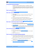
System Error Codes - Full Descriptions The following image shows the Formatter LEDs, which should be marked 1, 2, and 3. 1 2 3 Use the following table to interpret the LEDs and find the source of the problem. Remember that you should read these LEDs when you push the Power button. Some combinations may require the replacement of two or more components. In this case, always replace one component at a time. Test the printer to see if the problem has disappeared (check the LEDs again).
System Error Codes 1. Front Panel Page 6-47 2. Formatter Page 6-200 8 On On On X On 3. Main PCA Page 6-205 4. Front panel cable Page 6-47 9 On On On On Off System Error: 11:YZ Problem Description: Trailing Cable does not seem to be detected. Front Panel Page 6-47 Corrective Action: Try the following: 1 Switch the Power OFF from the back of the Printer and disconnect the Power cord. Reconnect the power cord and power On the Printer. 2 Check that the Trailing Cable is not damaged.
System Error Codes - Full Descriptions 4 If the System Error continues, replace the Service Station. See Service Station (T1100/T1100ps/T610) on page 6-61 or Service Station (T1120/ T1120ps) on page 6-65. 5 If the System Error continues, replace the PrintMech PCA. See PrintMech PCA (T1100, T1100ps, T610 ONLY) on page 6-73. System Error: 21.1:YZ Problem Description: Fail moving the Primer Motor of the Service Station.
System Error Codes 2 Check that the cables between the Left Ink Supply Station and Main PCA the are not damaged and are correctly connected. 3 Perform the Ink Delivery System diagnostic test to troubleshoot the problem further. See 7. Ink Delivery System (IDS) on page 3-36. 4 If the System Error continues, replace the Left Ink Supply Station. See Left Ink Supply Station on page 6-183. 5 If the System Error continues, replace the Main PCA.
System Error Codes - Full Descriptions System Error: 31:02 Problem Description: An error has been detected with the cutter. Corrective Action: Try the following: 1 Switch the Power OFF from the back of the Printer and disconnect the Power cord. Reconnect the power cord and power On the Printer. 2 Check the Cutter Assembly for blockage or any other obvious problems. 3 Replace the Cutter Assembly. See Cutter Assembly on page 6-42. System Error: 31:03 Problem Description: Paper is loaded.
System Error Codes 7 If the System Error continues, replace the Main PCA. See Starwheel Assembly on page 6-208. System Error: 41.1:YZ Problem Description: Electrical fault or current limit in Media-Axis Motor. Corrective Action: Try the following: 1 Switch the Power OFF from the back of the Printer and disconnect the Power cord. Reconnect the power cord and power On the Printer. 2 Open the Window and check for any visible obstacles restricting the movement of the Media Advance Roller.
System Error Codes - Full Descriptions 5 Perform the Service Station diagnostic test to troubleshoot the problem further. See 8. Service Station on page 3-42. 6 Check that the Scan-Axis Motor cable is not damaged and is correctly connected to the PrintMech PCA. 7 Replace the Scan-Axis Motor. See Scan-Axis Motor (T1100/T1100ps/ T610) on page 6-142 or Scan-Axis Motor (T1120/T1120ps) on page 6146. 8 If the System Error continues, replace the PrintMech PCA.
System Error Codes System Error: 45:YZ Problem Description: An error with the Rewinder System has been detected. Corrective Action: Try the following: 1 Switch the Power OFF from the back of the Printer and disconnect the Power cord. Reconnect the power cord and power On the Printer. 2 Check that the Rewinder cable is not damaged and is correctly connected to the PrintMech PCA. 3 Check that the Right Spindle Holder (rewinder included) is correctly attached to and aligned with the Right Cover.
System Error Codes - Full Descriptions System Error: 48:YZ Problem Description: PPS system failure. Corrective Action: Try the following: 1 Switch the Power OFF from the back of the Printer and disconnect the Power cord. Reconnect the power cord and power On the Printer. 2 Check that the Pen to Paper Space (PPS) Solenoid cable is not damaged and is correctly connected to the PrintMech PCA. 3 Perform the Scan Axis PRS diagnostic test to troubleshoot the problem further. See PRS Test on page 3-9.
System Error Codes 5 Replace the Drop Detector. See Drop Detector on page 6-69. 6 Reset the Calibration Flag of the Drop Detector. See Drop Detector Calibration on page 4-12. 7 If the System Error continues, replace the PrintMech PCA. See PrintMech PCA (T1100, T1100ps, T610 ONLY) on page 6-73. System Error: 55:YZ Problem Description: Problem with the Line Sensor. The printer has detected a failure to access Line Sensor EEPROM).
System Error Codes - Full Descriptions 3 Check that the Printer has the latest Firmware version. If not, update the Firmware to the latest version. 4 Perform the Carriage Test to troubleshoot the problem further. See 4. Carriage Assembly on page 3-26. 5 If the System Error continues, replace the Line Sensor. See Line Sensor (T1100/T1100ps/T610) on page 6-152 or Line Sensor (T1120/T1120ps) on page 6-157.
System Error Codes 3 Check that the Printer has the latest Firmware version. If not, update the Firmware to the latest version. 4 If the System Error continues, replace the Formatter. See Formatter on page 6-200. System Error: 65:YZ Problem Description: Memory Driver Internal I/O error, I/O Socket Manager Internal I/O error. Corrective Action: Try the following: 1 Switch the Power OFF from the back of the Printer and disconnect the Power cord. Reconnect the power cord and power On the Printer.
System Error Codes - Full Descriptions The display list is not visible to the user. There has been a few cases where a print job that had a relatively small file size has triggered an out of memory message to be displayed. Print jobs like this typically have a large number of objects in them or have complex objects such as raster images with gradients or objects with multiple layers. Any print job that contains these type of images can result in a display list memory greater than 128MB.
System Error Codes options and then settings. In the Custom Print Quality Options pane, select Economode. If the Out of Memory message still persists, proceed to the next workaround. 5 Out of Memory issues can always be solved if the processing of the job can be performed before reaching the printer. This can be done by selecting ‘Send Job as Bitmap’. The main processing of the print job will then be performed by the computer. This means that more computer resources can be used to process the plot.
System Error Codes - Full Descriptions System Error: 71:19 For T1100/T1100ps/T610 printers, the backup NVM is located in the Printmech PCA. For T1120/T1120ps printers, the backup NVM is located in the Media Advance Encoder PCA. In all T Series printers, the main NVM is located in the Formatter service part. You MUST NEVER replace both the Formatter and the PrintMech PCA (T1100/T1100ps/T610) or Media Advance Encoder PCA (T1120/T1120ps) at the same time.
System Error Codes T1120ps) and Formatter EEROM. Choose which EEROM held the correct information, and copy it across to the other EEROM. New initialization process From firmware 7.x.x.x onwards, the information is now always copied automatically from the EEROM in the PrintMech PCA (T1100/T1100ps/ T610) or Media Advance Encoder PCA (T1120/T1120ps) to the EEEROM in the Formatter.
System Error Codes - Full Descriptions System Error: 73:YZ Problem Description: Servo Error. Corrective Action: Try the following: 1 Switch the Power OFF from the back of the Printer and disconnect the Power cord. Reconnect the power cord and power On the Printer. 2 Check that the Printer has the latest Firmware version. If not, update the Firmware to the latest version. 3 Perform the Scan Axis Test to troubleshoot the problem further. See 1. Scan Axis on page 3-6.
System Error Codes - Full Descriptions System Error: 75.22:YZ Problem Description: The spittoons (Left Spittoon, Service Station) are full. Corrective Action: Try the following: Use Preventive Maintenance Kit #2 to replace the Left Spitton and Service Station. System Error: 76:YZ Problem Description: Hard disk drive is full. Corrective Action: Try the following: Remove any unnecessary files from the hard disk using the web server.
System Error Codes - Full Descriptions System Error: 79:YZ Problem Description: Generic Firmware error. Corrective Action: Try the following: 1 Switch the Power OFF from the back of the Printer and disconnect the Power cord. Reconnect the power cord and power On the Printer. 2 Check that the Printer has the latest Firmware version. If not, update the Firmware to the latest version. If you see system error 79:04, see Appendix A: How to troubleshoot SE 79:04 on page 2-33. System Error: 79.
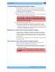
System Error Codes - Full Descriptions roller. A gap on the platen beam. If there’s any gap in Z (vertical direction) between the plastic feature of the platen and the metal side plate, then the chassis is damaged and the unit cannot be repaired. late Gap in Z p e d i tal s e M n late p c ti Plas Problem Description: Problem with paper advance. This source of error could come from an error in any of the following systems: paper motor, disk encoder, cables or main electronics.
System Error Codes - Full Descriptions 2 Perform the Media Drive diagnostic test to troubleshoot the problem further. See 2. Paper Drive on page 3-18. 3 If the printer has a 44 inch scan axis (and a Rewinder), perform the Rewinder diagnostic test to troubleshoot the problem further. See 6. Rewinder on page 3-34. 4 Check the connections on the Main PCA; the Media Advance Drive is connected to the connector labeled Paper Motor.
System Error Codes System Error: 87:YZ Problem Description: Problem finding the Scan-axis encoder reading. Corrective Action: Try the following: 1 Upgrade the firmware. 2 Clean the Encoder Strip. 3 Replace the Encoder Strip. See Encoder Strip, spring and attachment nut (T1100/T1100ps/T610) on page 6-96 or Encoder Strip, spring and attachment nut (T1120/T1120ps) on page 6-99. 4 Replace the Carriage PCA. See Carriage PCA (T1100/T1100ps/T610) on page 6-173 or Carriage PCA (T1120/T1120ps) on page 6-178.
Appendix A: How to troubleshoot SE 79:04 5 If the System Error continues, replace the Formatter. See Formatter on page 6-200. System Error: 94.1:YZ Problem Description: Profiling algorithm failed. Corrective Action: Try the following: 1 Profiling failed due to a different error (not algorithm / data processing). 2 Perform the Line Sensor calibration. 3 See The Line Sensor has Problems Detecting Media on page 1-5. 4 If the System Error continues, replace the Line Sensor.
Appendix A: How to troubleshoot SE 79:04 One important point to mention is that, although 79:04 system errors can be caused by a hardware malfunction, the vast majority of 79:04 system errors are pure software or firmware issues. In these cases the issue can only be solved by determining the root cause and implementing a solution. The solution can usually be applied by either correctly configuring a selection, updating the printer’s firmware/software that is being used or by fixing an error in the code).
Appendix A: How to troubleshoot SE 79:04 Solutions and workarounds When a job consistently generates a 79:04 system error, it is either because of a issue in the printer’s firmware or because of a defect in the job itself (when it has been generated by 3rd party SW). In order to identify the cause and find out a solution, these issues should always be immediately escalated to the GBU through the GCC.
System Error Codes c The printer can reboot normally d When the data is accessed again (typically, under the same conditions as in step “b”), the 79:04 system error is displayed again Solutions and workarounds Many times, data related 79:04 errors are resolved by means of hardware intervention. Since data is stored in physical components (RAM, EEROM and Hard Disk), replacing these components with new ones which are empty usually solves the problem.
Appendix A: How to troubleshoot SE 79:04 Network related SE79:04 Most HP Designjet printers have built-in networking capabilities. Network settings can be set manually, but in the majority of cases, they are obtained automatically from the printer. These settings include many different fields, such as IP address and subnet mask, available gateways, host and domain names, etc.
Appendix A: How to troubleshoot SE 79:04 These errors will most likely only happen in very specific corner cases that have not been identified during the development or the qualification of the printer, so normally, they do not severely impact the customer, as they do not affect their regular working flows. Symptoms The symptoms here are as numerous as the number of possible interactions between the user and the printer.
Appendix A: How to troubleshoot SE 79:04 checks the counter from time to time to see its value and take conclusions from it. If the counter is near 0, it means that the printer is processing correctly, and if it grows too big, it may mean that there is a bottleneck somewhere and maybe the JetDirect card throughput is decreased to control its speed to the printer.
System Error Codes Application/RIP/Driver settings Type of output files this application, RIP or driver is generating Some sample files that are representative of what the customer is using Operating System Method of connection to the printer A description of the normal flow when the issue occurs and the typical frequency of occurrence (i.e.
Appendix A: How to troubleshoot SE 79:04 Execute the troubleshooting for “data related” system errors, refer to page 3, Data related SE79:04 2 Replace the memory 3 Replace the HDD 4 Escalate the issue before replacing any additional parts. Troubleshooting based on symptoms This section will describe which troubleshooting steps to perform for a 79:04 system error based on the symptoms of the issue.
Appendix A: How to troubleshoot SE 79:04 Conditions where the problem occurs and conditions prior to the first occurrence of the problem The results of the previous 8 steps The System Error detailed information (this can be obtained by pressing CANCEL + Down) The printer logs. In order to obtain the printer logs, check the corresponding appendix. See Appendix C: Obtaining printer logs on page 2-46. Front panel displays 79:04 during printer operation – not while sending jobs 1 Reboot the printer.
Appendix A: How to troubleshoot SE 79:04 The printer information pages (either printed and faxed or obtained through the Embedded Web Server) The System Error detailed information (it can be obtained by pressing CANCEL + Down) The printer logs. In order to obtain the printer logs, check the corresponding appendix . See Appendix C: Obtaining printer logs on page 2-46. Front panel displays 79:04 while printing While printing a single job The error happens after a single job is sent.
Appendix A: How to troubleshoot SE 79:04 Conditions where the problem occurs and conditions prior to the first occurrence of the problem.
Appendix B: Updating firmware in diagnostics boot mode e If you are using the HP-GL/2 driver, try sending the job as a bitmap 5 If you are using a 3rd party application that does not print through the HP driver, try modifying the printing workflow by: a Using an HP driver b Changing the settings in the application’s printing dialog 6 Escalate the issue with the following information: Unit information: S/N, P/N, accessories The printer information pages (either printed and faxed or obtained through the E
System Error Codes b Configure the connection to send the data correctly: bin > hash 4 Upload the firmware file (> put ). Standard FMW files that are available in the customer website will not work with this method, since FMW files need to be uploaded through the EWS in order to work. You will need to use a firmware file in PLT format instead. You can obtain the PLT firmware for the latest available firmware versions in the LFP Customer Assurance website (http://bcnsite.bpo.hp.com/csw/).
Appendix C: Obtaining printer logs 5 The printer.log file contains the logs of the printer activity since the last time the printer was rebooted. Previous logs are automatically compressed when the printer reboots, and are stored in .gz files which contain the date and time of the reboot in the file name. If you are interested in getting traces of the printer activity before the last reboot, you should download these .gz files as well.
System Error Codes 2-48 HP Designjet T Series — Service Manual
Service Tests and Utilities 2 3 Introduction 3-2 Diagnostics - Self Test 3-2 Service Tests (Diagnostics) 3-3 Using the Front Panel 3-5 Entering the Service Tests Menu 3-6 1. Scan Axis 3-6 2. Paper Drive 3-18 3. Electronics Module 3-21 4. Carriage Assembly 3-26 5. Sensors 3-31 6. Rewinder 3-34 7. Ink Delivery System (IDS) 3-36 8. Service Station 3-42 9. I/O Information 3-48 10. Unit Information 3-49 11. EEROM Reset 3-50 12. Set Unit Configuration 3-51 13. Error 71:19 Recovery 3-51 14.
Service Tests and Utilities Introduction This chapter explains how to use the built-in Service Tests and Service Utilities and what to do if any of the Service Tests FAIL. If possible, always perform a Service Test on the component that you are about to replace, just to make sure that is the component that has FAILed. If the test on that component passes, there is no need to replace it.
Service Tests (Diagnostics) Service Tests (Diagnostics) The following is a list of all internal Service Tests available in the Printer. For instructions on entering the Service Tests menu see Entering the Service Tests Menu on page 3-6. 1 Scan Axis Test. See 1. Scan Axis on page 3-6 The purpose of this test is to verify the operation of components related to the Scan Axis. The tests verify the operation of the: PRS Scan Axis Star Wheel Lifter Cutter 2 Paper Drive Test. See 2.
Service Tests and Utilities This option allows you to view the Firmware Version, Part Number, and Serial Number of the Printer. 11 EEROM Reset. See 11. EEROM Reset on page 3-50 The purpose of this test is to reset the EEROM values. 12 Set Unit Configuration. See 12. Set Unit Configuration on page 3-51 Not implemented. 13 Error 71:19 Recovery. See 13.
Service Tests (Diagnostics) Using the Front Panel Below is a diagram of the front panel. View Loaded Paper Arrow keys View Ink Levels Cancel OK Power Form Feed and Cut Unload Paper Menu Back Key Function Arrow Keys Use the Arrow keys to scroll through a menu or toggle between YES or NO when prompted. Cancel Use the Cancel key to abort or stop a procedure or reject test results. OK Use the OK key to select a menu option. Power Use the Power key to turn the printer ON and OFF.
Service Tests and Utilities Entering the Service Tests Menu In order to enter the Service Utility Menu, see Entering the Service Utilities Menu on page 3-57. 1 Make sure the printer is switched OFF from the power switch on the front of the printer and NOT from the power switch on the back of the printer. 2 For On-Site Engineers, hold the Up arrow key and the OK key down and switch the printer ON using the front power switch.
Service Tests (Diagnostics) System System System System Error Error Error Error Code 42:XZ. Code 47:XZ. Code 73:XZ. Codes related to Scan-Axis shutdown or Carriage jam. Diagnostic tests also need to be performed after removing or replacing certain printer components. If you have removed or replaced printer components, check the Service Calibration Guide to Removal and Installation on page 6-5 to see which tests and calibrations you need to perform.
Service Tests and Utilities 4 The printer then starts the Star wheel lifter PWM control test to verify the subsystem. As the test executes the Front Panel displays the following messages: Starting Horsburgh & Mips. Starting nvm Starting Tests PWM. Starting Tests GPIO. Booting up the Carriage. Starting SVS Motor Starting Carriage Motor. Starting Service Station. Starting Scan Axis. Moving SVS out of Scan. Homing Scan Axis. Move Carriage out of SVS path.
Service Tests (Diagnostics) If there is a Failure at any point during the test, the Front Panel will display the relevant System Error Code. To trouble shoot any displayed error codes, see System Error Codes - Full Descriptions on page 2-7. 7 Once the test has been completed the Front Panel displays the test results. 8 Press any key to finish. 9 The Front Panel shows the test complete display for a few seconds. 10 The Front Panel prompts you to shutdown the printer to complete the test.
Service Tests and Utilities 2 The Front Panel will show the 1. Scan Axis submenu. 3 In the Scan Axis submenu, scroll to PRS and press OK to start the test. The Printer will start the Scan Axis subsystem Common Initialization and PRS test initialization. If there is a Failure at any point during the tests, the Front Panel will display the relevant System Error Code. To trouble shoot any displayed error codes, see System Error Codes - Full Descriptions on page 27.
Service Tests (Diagnostics) 5 Once the test has completed, the Front Panel prompts you to confirm that the PRS moved. 6 If the PRS moved, press OK to accept the results. If the PRS did not move, press Back or Cancel to reject the results and exit the test. 7 The Front Panel shows the test complete display for a few seconds. 8 The Front Panel prompts you to shutdown the printer to complete the test. 9 Press any key to shutdown the printer.
Service Tests and Utilities 2 The Front Panel will show the 1. Scan Axis submenu. 3 In the Scan Axis submenu, scroll to Scan Axis and press OK to start the test. The Printer will start the Scan Axis subsystem Common Initialization. If there is a Failure at any point during the tests, the Front Panel will display the relevant System Error Code. To trouble shoot any displayed error codes, seesee System Error Codes - Full Descriptions on page 2-7. 4 The printer then starts the Scan Axis test initialization.
Service Tests (Diagnostics) 8 The Front Panel prompts you to confirm that the carriage supply LED is switched on. 9 Open the Window and verify that the LED is on. The LED can be seen through the slots in the carriage cover. 10 Press OK if the LED is on. If the LED is not on or use the Arrow keys to select NO and press OK.. 11 The printer then continues the Scan Axis test. As the test executes the Front Panel displays the following messages: Booting Up Carriage. Starting SVS Motor.
Service Tests and Utilities Preparing SVS. Prog slow PWM scan. Moving Carriage middle. Starting Carriage Encoder. Prog fast PWM scan 19 The Front Panel prompts you to move the carriage to check the encoder readings. 20 Use the Arrow keys to move the Carriage left or right as prompted to by the Front Panel. 21 Repeat step 20 to complete the ten Carriage movements used to check the encoder. 22 The Front Panel displays the encoder check results. 23 Press any key to continue.
Service Tests (Diagnostics) 26 Press any key to continue. 27 The printer then continues with the PWM test. As the test executes the Front Panel displays the following messages: Starting PpsMotor. Starting Scan Axis. Doing PWM test. 28 The Front Panel displays the PWM check results and prompts you to confirm or reject the test results. The PWM Average should be between 0 and 18750. The PWM min diff limit should be greater than or equal to 40.
Service Tests and Utilities 35 Press any key to shutdown the printer. Cutter test The Cutter is designed to cut roll media after printing for the size of sheet defined. Before executing this test you should run the Scan Axis, Media Drive and Carriage tests to ensure that each of these subsystems is operating correctly. Perform the Scan Axis - Cutter test as follows: 1 In the Diagnostics menu, scroll to 1. Scan Axis and press OK. 2 The Front Panel will show the 1. Scan Axis submenu.
Service Tests (Diagnostics) Uncapping Service Station. Starting Cutter. Starting PaperMotor. Starting Media Sensor. Reading Media Presence. 5 If paper is already loaded, the printer detects the paper and continues the test. If paper is NOT loaded, the Front Panel prompts you to load roll media. 6 Raise the Media Lever, load roll media, lower the Media Lever, and press any key to continue. 7 The printer then starts an actual test cut of the media.
Service Tests and Utilities 11 The Front Panel prompts you to shutdown the printer to complete the test. 12 Press any key to shutdown the printer. 2. Paper Drive The Paper Drive test diagnoses Failures of components of the Media-Axis. You must perform the Paper Drive Test after: System Error Code 81:XZ. System Error Code 41:XZ. System Error Code 73:XZ. Diagnostic tests also need to be performed after removing or replacing certain printer components.
Service Tests (Diagnostics) Starting Nvm Starting Tests PWM. Starting Tests GPIO. Booting up the Carriage. Starting DelSol1. Starting Carriage. Getting Part Number. Part Number Checking PCA Rev 3 The Front Panel then displays the Main PCA Revision and prompts you to press any key to continue. The Main PCA Revision should be greater than .15. 4 Press any key to continue. 5 The Front Panel displays the following messages: Prog slow PWM paper.
Service Tests and Utilities 11 The Front Panel then displays the Open Loop UNROLL test result. 12 Press any key to continue. 13 The Front Panel then displays: Starting Paper Motor. Starting Paper Axis. Calib. Analog Decoder. 14 The Front Panel then displays the Analog Decoder calibration results. The The The The GAIN for channel A must be between 0 and 3.5. GAIN for channel B must be between 0 and 4.5. OFFSET for channel A must be between -63.5 and 63.5.
Service Tests (Diagnostics) The PWM StDev results must be between 0 and 500. The PWM max results must be between 15000 and 20000. 22 If the results are correct, press OK to accept the results. If the results are not correct, press Back/Cancel to reject the results and FAIL the test. 23 If you accept the results, the Front Panel shows the test complete display for a few seconds: 24 The Front Panel prompts you to shutdown the printer to complete the test. 25 Press any key to shutdown the printer. 3.
Service Tests and Utilities 1 In the Diagnostics menu, scroll to 2. Electronics Module and press OK. 2 The printer starts the Electronics Module test and displays the following messages: Starting Horsburgh and Mips. Starting Nvm. Accessing Nvm. 3 The printer starts the Electronics Module test to verify the subsystem and prompts you to test the Power Supply: 4 Press OK to the test the Power Supply. If you do not wish to test the power supply use the Arrow keys to select NO and press OK.
Service Tests (Diagnostics) 9 The Front Panel then displays the Fan Speed test result and prompts you to press any key to continue. 10 Press any key to continue. 11 The Front Panel then prompts you to test the Formatter. 12 Press OK to the test the Formatter. If you do not wish to test the Formatter use the Arrow keys to select NO and press OK. 13 The Formatter voltage test starts and the front Panel displays the following messages: Starting DelSol1. Getting PCA revision.
Service Tests and Utilities 19 The Formatter hard disk test starts and the Front Panel displays the following messages: Getting HDA info. 20 The Front Panel then displays Formatter Hard Disk information test results and prompts you to press any key to continue. 21 Press any key to continue. 22 The Formatter hard disk file information test starts and the Front Panel displays the following messages: Getting File System Info.
Service Tests (Diagnostics) 29 The Front Panel then displays Main Memory size test results and prompts you to press any key to continue. 30 Press any key to continue. 31 The Front Panel then prompts you to test the Formatter Communications. 32 Press OK to the test the Formatter. If you do not wish to test the Formatter use the Arrow keys to select NO and press OK. 33 The Formatter Communications test starts and the front Panel displays the following messages: Starting Micci2Bus.
Service Tests and Utilities Getting Plotter info. 39 The Front Panel then displays the Plotter Information results and prompts you to press any key to finish. 40 Press any key to finish. 41 The Front Panel shows the test complete display for a few seconds. 42 The Front Panel prompts you to shutdown the printer to complete the test. 43 Press any key to shutdown the printer. 4. Carriage Assembly The Carriage assembly test diagnoses Failures of any components of the Carriage.
Service Tests (Diagnostics) Starting Horsburgh. Starting Nvm. Accessing Nvm. Starting AdcManagerHorus. Starting Carriage. Getting Carriage PCA Rev. 3 The Front Panel prompts you to verify the Carriage Assembly PCA revision. The PCA Rev must be between 0.949 and 1.161. 4 If the results are correct, press OK to accept the results. If the results are not correct, press Back/Cancel to reject the results and FAIL the test.
Service Tests and Utilities Getting Vpp. 12 The Front Panel then displays the Pens Voltage test results. The result must be between 26.5 and 33 Volts. 13 If the results are correct, press OK to accept the results. If the results are not correct, press Back/Cancel to reject the results and FAIL the test. 14 The Carriage Assembly test continues and the Front Panel displays: Starting Line Sensor Leds. Starting LightSensor. Starting LineSensing. Starting SVS Motor. Starting Carriage Motor.
Service Tests (Diagnostics) Reading LS Nvm. Writing new LS Nvm. Checking LS Serial Number. Restoring LS Serial Number. Starting Service Station. Starting Scan Axis. Moving SVS out of sax. Homing Scan Axis. Moving Carriage out of SVS. Homing Service Station. Starting Servicing Services. Capping Service Station Uncapping Service Moving to Pen postion. Reading Pen presence. 19 The Carriage moves into the print path and the front Panel then prompts you to remove all pens.
Service Tests and Utilities 31 The Front Panel then displays the test result. 32 Press any key to continue. 33 The printer continues the test, and the Front Panel displays: Preparing Pen initialization. Checking Pen status 34 The Front Panel then displays the test result. 35 The Encoder Manager test starts and the Front Panel displays: Starting EncoderManager. Moving Carriage center. Setting Encoder. Reading Encoder position. Moving Carriage to left. Reading Encoder position.
Service Tests (Diagnostics) 37 Press any key to finish. 38 The Front Panel shows the test complete display for a few seconds. 39 The Front Panel prompts you to shutdown the printer to complete the test. 40 Press any key to shutdown the printer. 5. Sensors The Sensors test diagnoses Failures of any sensors of the printer. Always run this test before replacing any of the following sensors: Window sensor. Media Lever position sensor.
Service Tests and Utilities 3 The Sensors test starts and the Front Panel prompts you to verify default sensor positions: 4 Verify that the sensors are in the default positions and any key to continue. 5 The Window sensor test starts and the Front Panel prompts you to open the Window: 6 Open the Window. 7 Press any key to continue. 8 The Window sensor test continues and the Front Panel prompts you to close the Window: 9 Close the Window. 10 Press any key to continue.
Service Tests (Diagnostics) 14 The Media Lever sensor test continues and the Front Panel prompts you to lower the Media Lever: 15 Lower the Media Lever. 16 Press any key to continue. 17 The Media sensor test starts and the Front Panel prompts you load media: 18 Raise the Media Lever. 19 Load media. 20 Lower the Media Lever. 21 Press any key to continue. 22 The Media sensor test continues and the Front Panel prompts to remove media: 23 Raise the Media Lever. 24 Unload the media. 25 Lower the Media Lever.
Service Tests and Utilities 28 The Front Panel prompts you to shutdown the printer to complete the test. 29 Press any key to shutdown the printer. 6. Rewinder The Rewinder test diagnoses failures of the Rewinder located in the Paper Path Assemblies (Rear). Always run this test before replacing the Right Spindle Holder (rewinder included). The Rewinder is only available on the 44 inch printers. The 24 inch printers do NOT have a Rewinder.
Service Tests (Diagnostics) If there is a Failure at any point during the tests, the Front Panel will display the relevant System Error Code. To trouble shoot any displayed error codes, see System Error Codes - Full Descriptions on page 2-7. 2 The Rewinder test starts and the front Panel displays the following messages: Starting Horsburgh.
Service Tests and Utilities Once you have completed the Rewinder diagnostic test, you must perform a Paper Advance Calibration. Paper Advance Calibration on page 4-6. 7. Ink Delivery System (IDS) The complete Ink Delivery System test consists of individual tests for the different components related to this subsystem. These tests are: Ink Delivery System Check Ink Supplies Check Leakage Diagnostic tests also need to be performed after removing or replacing certain printer components.
Service Tests (Diagnostics) 6 Press OK to continue. 7 The test continues and the front Panel displays the following messages: Starting Horsburgh0. Starting Mips. Starting Nvm. Getting Part Number. Starting ISS Motors. Moving Bongos down. Reading Bongos down. Moving Bongos up. Reading Bongos up. Starting OutOfInk sensors. Reading OutOfInk. 8 The Front Panel then prompts you push down Bongo0. 9 Press and hold down Bongo0 which is located at the furthest left Ink Cartridge position.
Service Tests and Utilities 17 Install all the Ink Cartridges. 18 Press OK to continue. 19 The Acumen Supplies test and the front Panel displays the following messages: Starting AcumenSupplies. Reading AcumenSupplies. 20 The Front Panel then displays Acumen Supplies test results. 21 The Front Panel shows the test complete display for a few seconds. 22 The Front Panel prompts you to shutdown the printer to complete the test. 23 Press any key to shutdown the printer.
Service Tests (Diagnostics) 2 The Front Panel will show the 7. IDS submenu. 3 In the IDS submenu, scroll to Check Ink Supplies and press OK to start the test. 4 The Check Ink Supplies test starts and the front Panel displays the following messages: Starting Horburgh & Mips. Starting Nvm. Getting Part Number. Starting Supplies. Starting AcumenSupplies. Reading Ink Supplies. 5 The Front Panel then displays Check Ink Supplies test results Use the Arrow keys to view the second results screen.
Service Tests and Utilities 8 The Front Panel prompts you to shutdown the printer to complete the test. 9 Press any key to shutdown the printer. Check Leakage 1 In the Diagnostics menu, scroll to 7. IDS and press OK. 2 The Front Panel will show the 7. IDS submenu. 3 In the IDS submenu, scroll to Check Leakage and press OK to start the test. 4 The Ink Delivery System test starts and the front Panel prompts you to remove all the Ink Supplies.
Service Tests (Diagnostics) 6 While the printer moves the Bongos down, the Front Panel displays the following message: 7 If a Bongo remains in the UP position, use your finger to help push it down. The test continues and displays the following messages: Reading DDI Sensors Moving Bongos up Reading DDI Sensors Moving Bongos down 8 The front Panel prompts you to insert all the Ink Supplies. 9 Install all the Ink Cartridges. 10 Press OK to continue.
Service Tests and Utilities 14 The Front Panel prompts you to shutdown the printer to complete the test. 15 Press any key to shutdown the printer. 8. Service Station The complete Service Station test consists of individual tests for the different components related to this subsystem. These tests are: Service Station Primer Motor Aerosol Fan Diagnostic tests also need to be performed after removing or replacing certain printer components.
Service Tests (Diagnostics) Starting SVS Motor. Starting Carriage Motor Getting Part Number. Starting Service Station. Starting Scan Axis. Moving SVS out of Sax. Homing Scan Axis. Moving Carriage out of SVS. Homing Service Station. Moving to Spit Rear pos. Moving to Spit Front pos. Moving to Wipe forward pos. Moving to Wipe reverse pos. Moving to Cleaner pos. Moving to SOL pos. Moving to PEG pos. Homing Scan Axis. Starting ServicingServices.
Service Tests and Utilities 9 The Front Panel then asks if you want to cap the Service Station. 10 Select YES to cap the Service Station or NO to skip this test. 11 The test continues and displays the following messages: Capping Service Station. 12 The Front Panel displays the Service Station test results. 13 Press any key to finish the test. 14 The Front Panel shows the test complete display for a few seconds. 15 The Front Panel prompts you to shutdown the printer to complete the test.
Service Tests (Diagnostics) 2 The Front Panel will show the 8. Service Station submenu. 3 In the 8. Service Station submenu, scroll to Primer Motor and press OK to start the test. 4 The Primer Motor test starts and the front Panel displays the following messages: Starting Horsburgh and Mips. Starting Nvm. Getting Part Number. Starting Service Station. Starting Scan Axis. Moving SVS out of Sax. Homing Scan Axis. Moving Carriage out of SVS. Homing Service Station.
Service Tests and Utilities 6 The Front Panel prompts you to shutdown the printer to complete the test. 7 Press any key to shutdown the printer. Aerosol Fan The Aerosol Fan diagnostic test is only available for printers that include an aerosol fan. 1 In the Diagnostics menu, scroll to 8. Service Station and press OK. 2 The Front Panel will show the 8. Service Station submenu. 3 In the 8. Service Station submenu, scroll to Aerosol Fan and press OK to start the test.
Service Tests (Diagnostics) 6 Press OK to switch on the Aerosol Fan. If you do not wish to switch on the Aerosol Fan use the Arrow keys to select NO and press OK. 7 The test continues and the Front Panel displays the following message: Turning on Aerosol Fan. 8 The Front Panel then displays the results. 9 Press any key to continue. 10 The front panel prompts you to check if the Aerosol Fan is operating. 11 Listen carefully to check if the Aerosol Fan is operating.
Service Tests and Utilities 17 The Front Panel prompts you to shutdown the printer to complete the test. 18 Press any key to shutdown the printer. 9. I/O Information The I/O Information test retrieves the TC/IP Network configuration parameters from the printer. 1 In the Diagnostics menu, scroll to 9. I/O Information and press OK. 2 The Front Panel displays the I/O Information. 3 Press any key to finish. 4 The Front Panel shows the test complete display for a few seconds.
Service Tests (Diagnostics) 10. Unit Information 1 The Unit Info test retrieves the Firmware Version, Serial Number and Part Number of the printer. 2 In the Diagnostics menu, scroll to 10. Unit Information and press OK. 3 The Unit Information test starts and the front Panel displays the following message: Starting Horsburgh and Mips. Starting Nvm. Getting FW version. Getting Serial Number Getting Part Number. 4 The Front Panel shows the result of the test. 5 Press any key to continue.
Service Tests and Utilities 11. EEROM Reset The EEROM Reset test resets the printer to the factory defaults and delete any user information/files. 1 In the Diagnostics menu, scroll to 11. EEROM and press OK. 2 The EEROM Reset test starts and the front Panel prompts you to request if you want to continue. 3 If you do want to continue the test, use the Arrow keys to select YES and press OK. If you do NOT want to continue, select NO and press OK.
Service Tests (Diagnostics) 7 The Front Panel prompts you to shutdown the printer to complete the test. 8 Press any key to shutdown the printer. 9 Recover the Printheads. See Chapter 1 Image Quality Maintenance Procedure on page 1-49. 12. Set Unit Configuration This diagnostic test is not available. 13.
Service Tests and Utilities 2 The Front Panel will show the 13. Error 71:19 Recovery submenu. 3 In the 13. Error 71:19 Recovery submenu, scroll to Set Serial Number and press OK to start the test. 4 The Set Serial Number test starts and the front Panel displays the following messages: Checking SE Log. Starting Horsburgh & Mips. Starting NvmBackup. Starting NvmMain Getting Serial Number Checking Serial Number. Starting Nvm. Getting Part Number.
Service Tests (Diagnostics) 9 Once you have confirmed the new Serial Number, the Front Panel prompts you to change the part number of the unit. 10 If you want to change the Part Number of the unit, select YES. If you do not want to change the Part Number, select NO. 11 If you selected YES to change the Part Number, the Front Panel prompts you to select from a list of allowed Part Numbers. 12 Use the arrow keys to scroll through the allowed Part Numbers and press OK to select the Part Number.
Service Tests and Utilities Select Right S/N 1 In the Diagnostics menu, scroll to 13. Error 71:19 Recovery and press OK. 2 The Front Panel will show the 13. Error 71:19 Recovery submenu. 3 In the 13. Error 71:19 Recovery submenu, scroll to Select Right S/N and press OK to start the test. 4 The Select Right S/N test starts and the front Panel displays the following message: Checking SE Log. Starting Horsburgh and Mips. Starting NvmMain Starting NvmBackup. Getting Serial Number.
Service Tests (Diagnostics) 7 Press any key to shutdown the printer. 14. Others This test is not implemented for the current version of the printer.
Service Tests and Utilities Service Utilities The following is a list of all internal Service Utilities available in the Printers. For instructions on entering the Service Utilities menu, see Entering the Service Utilities Menu on page 3-57. 1 Turn Drive Roller. See 1. Turn Drive Roller on page 3-58. The purpose of this Service Utility is to rotate the Drive Roller and the Overdrive in order to clean them. 2 Purge Tubes. See 2. Purge Tubes on page 3-60.
Service Utilities 13 Enable Hide Front Panel Information. See 13. Enable Hide Front Panel Information on page 3-73. 14 Enable/Disable Port 280. See 14. Enable/Disable Port 280 on page 3-73. Entering the Service Utilities Menu 1 Once the message “Ready” or “Ready for paper” is displayed on the frontpanel, press the Menu key.
Service Tests and Utilities 5 Use the Arrow keys to scroll through the “Service Utilities” selections and press the OK key to begin a specific operation when the required Service Utility is highlighted. If the printer is not used for 135 seconds, the printer exits out of the Service Utilities Menu and you must repeat the above steps to enter Service Utilities again. In some cases a quick press of a button may not be recognized by the Printer.
Service Utilities BEFORE PERFORMING THIS SERVICE UTILITY, OPEN THE WINDOW. WITH A FOLDED PIECE OF PAPER, ACTIVATE THE MECHANICAL WINDOW SENSOR. THE PAPER SHOULD FIT TIGHTLY SO IT DOES NOT FALL INTO THE SENSOR. Perform the Turn Drive Roller utility as follows: 1 In the Service Utilities submenu, scroll to Turn Drive Roller and press OK. 2 The test begins and the Front Panel displays the following message: Checking Media Presence Sensor 3 If media is loaded, the service utility will be cancelled.
Service Tests and Utilities 6 Once you have finished cleaning the Drive Roller and the Overdrive, press the Cancel key to finish the utility. 7 If the utility exits correctly, OK will be displayed on the Front Panel. REMEMBER TO REMOVE THE PIECE OF PAPER FROM THE WINDOW SENSOR BEFORE CLOSING THE WINDOW AS THIS COULD DAMAGE THE WINDOW AND THE SENSOR. 2.
Service Utilities 2 The Front Panel prompts you to confirm that the dummy printheads are correctly inserted. If the dummy printheads are correctly inserted, press OK. If you have not inserted the dummy printheads, press BACK or CANCEL to exit the test. Insert the dummy printheads using the Change Printheads procedure. Changing a Printhead on page 3-12 3 The Front Panel displays a message to say the Printer is going to reboot.
Service Tests and Utilities 7 The Front Panel then prompts you to remove the Setup Printheads and install the Printheads. 8 Remove ALL the Setup Printheads from the Carriage and install the previously removed Printheads. 9 Once ALL the Printheads are installed, the Front Panel will instruct you to close the Carriage cover and close the Window.
Service Utilities 2 The Printer will display the current Serial Number and the new Serial Number of the Printer. Use the Up and Down keys to go through the digits and press the OK key to go to the next digit. You can press the Cancel key at any time to exit the utility without making any changes. If the Serial Number or the Part Number cannot be read, the Front Panel will display the relevant System Error code. See System Error Codes - Full Descriptions on page 2-7.
Service Tests and Utilities Select Reset usage counters to reset the Life Counter of a single part. a If you select Reset Maintenance usage, which will reset the Life Counter for ALL parts included in a Preventive Maintenance Kit (PMK), you can choose from the following Preventive Maintenance Kits: Preventive Maintenance Kit 1 (PMK1). See Preventive Maintenance Kit #1 on page 7-5. Preventive Maintenance Kit 2 (PMK2). See Preventive Maintenance Kit #2 on page 7-6. Preventive Maintenance Kit 3 (PMK3).
Service Utilities If the Usage Counter information cannot be read, the Front Panel will display “Unable to get usage counter”. This could be a possible Firmware error. In this case, make sure you have the latest version of the Firmware. 4 If the utility exits correctly, OK will be displayed on the Front Panel. 5. Diagnostic Print The purpose of this Service Utility is to print the Diagnostic Print in order to identify Print Quality problems.
Service Utilities digit. You can press the Cancel key at any time to exit the utility without making any changes. 3 Once the new time has been entered, the Front Panel prompts you to confirm the new date and time. 4 Press OK to confirm the new date and time. Press BACK to modify the new date and time. Press CANCEL to exit without changing the date and time. 5 Once the new time has been confirmed, the Front Panel will prompt you to shut down the printer.
Service Utilities Getting Information of Firewall. 3 When the following message appears on the front panel, you must select whether you would like to enable or disable the firewall. Use the Up and Down keys to make your selection and press the OK key. 4 The system upgrades the internal memory to reflect the chosen selection. 5 The Front Panel shows the test complete display for a few seconds. 8.
Service Utilities 2 The Front Panel prompts you to confirm that you would like to reset the user life counters. 3 Press OK to reset the user life counters. If you are not sure, press BACK/ CANCEL to exit this utility. 4 The Front Panel shows the test complete display for a few seconds. 9. Enable/Disable Sleep Mode 1 In the Service Utilities submenu, scroll to "Enable/Disable Sleep Mode" and press OK. 2 Use the Up and Down keys to select enable or disable and press OK to confirm your selection.
Service Utilities 10. Disk Wipe DoD 5220.22OM The purpose of this Service Utility is to securely erase data on the Hard Disk according to the directive DoD 5220.22-M. The printer's hard disk is used as a temporary storage area for print jobs. The Secure Disk Wipe utility can erase your information from the hard disk to prevent unauthorized access. Secure Disk Wipe provides three different levels of security: Unsecure Mode: all pointers to the information are erased.
Service Tests and Utilities 3 In the Secure Sanitize Level submenu, scroll to the required Sanity Level and press Enter. Erasing the Hard Disk drive using either of the Secure Sanitize Levels is a very slow process, 6 hours for the 1 Pass mode and 40 hours for the 5 Pass mode. 4 The Front Panel displays the OK once the setting has been changed, and then returns you to the submenu. 5 In the Disk Wipe DoD 5330.22-M submenu, scroll to "Disk Wipe DoD 5330.22-M" and press Enter.
Service Utilities 7 When the following message appears on the Front Panel, you must select whether you want to continue and completely erase of the Hard Disk Drive by pressing Enter. Press Back or Cancel to exit the utility. 8 The erase process starts and the Front Panel shows a setup progress bar. 9 The printer reboots into the Disk Wipe mode, and continues with the disk erase until it is completed. Do NOT interrupt this process. All Front Panel buttons are disabled while printer erases the HDD.
Service Tests and Utilities 2 Use the Up and Down keys to select enable or disable and press OK to confirm your selection. 3 The Front Panel displays the OK screen and then returns you to the service utilities submenu. 12. New Left Spittoon The new left spittoon setting must be enabled in order to purge the left spittoon. On T610/T1100 printers this utility is automatially disabled, but can be enabled by replacing the left spittoon and enabling this option.
Service Utilities 3 The Front Panel displays the OK screen and then returns you to the service utilities submenu. 13. Enable Hide Front Panel Information The purpose of this utility is to hide the IP address and connection information that is normally visible on the Front Panel. The test is used for security purposes. 1 In the Service Utilities submenu, scroll to "Enable Hide FP Information" and press OK. 2 Use the Up and Down keys to select On or Off and press OK to confirm your selection.
Service Utilities 2 Use the Up and Down keys to select Enable or Disable and press OK to confirm your selection. 3 The Front Panel returns you to the service utilities submenu.
Service Tests Service Tests Entering the Service Tests Menu 1 Once the message “Ready” or “Ready for paper” is displayed on the frontpanel, press the Menu key. For information regarding the front panel buttons, Using the Front Panel on page 3-5 2 To have the user to perform certain Service Utilities, once inside the “Main Menu”, press the Down arrow key and the Cancel key together. You are now in the Service Tools Menu.
Service Tests and Utilities 5 Use the Arrow keys to scroll through the “Service Utilities” selections and press the OK key to begin a specific operation when the required Service Utility is highlighted. If the printer is not used for 135 seconds, the printer exits out of the Service Utilities Menu and you must repeat the above steps to enter Service Utilities again. In some cases a quick press of a button may not be recognized by the Printer.
Service Tests 1 In the Service Tests submenu, scroll to "Enable Hide FP Information" and press OK. 2 The Front Panel asks you if you want to proceed with the I/O test. 3 Press OK to proceed or Back/Cancel to exit. 4 The Front panel displays the I/O information. 5 Press any key to continue. 6 The printer tests the I/O interfaces, displays the OK screen, and returns you to the Service Tests submenu.
Service Tests and Utilities 3-78 HP Designjet T Series — Service Manual
Service Calibrations 3 4 Service Calibrations 4-2 Using the Front Panel 4-3 Entering the Service Calibrations Menu 4-4 Scan Axis Calibration 4-4 Service Station Calibration 4-5 Paper Advance Calibration 4-6 Drop Detector Calibration 4-12 Line Sensor Calibration 4-15 Carriage PCA 4-18 HP Designjet T Series — Service Manual 4-1
Service Calibrations Service Calibrations The Printer has several calibration procedures that must be performed under certain conditions. REMEMBER THAT CERTAIN CALIBRATIONS ARE REQUIRED EVEN IF AN ASSEMBLY HAS BEEN DISASSEMBLED TO GAIN ACCESS TO ANOTHER ASSEMBLY OR COMPONENT. The following is a list of all internal service calibrations available in the Printers. For instructions to enter the service calibrations menu, see Entering the Service Calibrations Menu on page 4-4. 1 Scan Axis Calibration.
Service Calibrations Using the Front Panel Below is a diagram of the front panel. View Loaded Paper Arrow Keys View Ink Levels Cancel OK Power Form Feed and Cut Unload Paper Menu Back Key Function Arrow Keys Use the Arrow keys to scroll through a menu or toggle between YES or NO when prompted. Cancel Use the Cancel key to abort or stop a procedure or reject test results. OK Use the OK key to select a menu option. Power Use the Power key to turn the printer ON and OFF.
Service Calibrations Entering the Service Calibrations Menu 1 Once the message “Ready” or “Ready for paper” is displayed on the frontpanel, press the Menu key. 2 To have the user to perform certain Service Utilities, once inside the “Main Menu”, press the Down arrow key and the Cancel key together. You are now in the Service Tools Menu. ON PH ES RT PO P U 3 For On-Site Engineers, once inside the “Main Menu”, press the Up arrow key and the Cancel key together. You are now in the Service Menu Menu.
Service Calibrations position to the Black Printhead. This calibration is integrated into the Scan Axis diagnostic test. See 1. Scan Axis on page 3-6. Perform the Scan Axis Calibration as follows: Make sure you load one of the following media into the Printer before performing this calibration: HP Bond Paper. HP Glossy Media. HP Coated Paper. HP Productivity Photo Gloss. HP Heavyweight Coated Paper. HP Super Heavyweight Coated Paper. HP Bright White Inkjet Paper.
Service Calibrations 2 To calibrate the Service Station, run the Service Station diagnostic test. See 8. Service Station on page 3-42. Paper Advance Calibration The purpose of this Service Calibration is to calibrate the nominal advance of the media. This calibration is necessary to control the exact movement of the media in order to avoid print quality problems like banding.
Service Calibrations Perform the Paper Advance Calibration as follows: Make sure that you unload media from the Printer before performing the Paper Advance Calibration. 1 In the Service Calibrations submenu, scroll to “Paper Advance Calibration” and press OK. 2 In the Paper Advance Calibration submenu, scroll to Print Calibration Pattern and press OK. 3 When the following message appears on the front panel, you must select whether you would like to continue with the calibration by pressing the OK key.
Service Calibrations Retry the Paper Advance Calibration. 6 Once the Analog Encoder has been calibrated correctly, the Front Panel prompts you to select the type of media you will use. Use the Arrow keys to choose ROLL or SHEET media. Press the OK key to start the media load process. 7 The Front Panel prompts you to select the paper category you will use for the calibration. Use the Arrow keys to scroll to your paper category and press the OK key to continue the media load process.
Service Calibrations prevent any back tension which could cause any media advance problems. Press the OK key to continue. 11 The Printer advances and reels in about a meter of paper. The Front Panel displays the following messages: Advancing Paper Printing Pattern 12 The Printer will start to print the Paper Advance Calibration Pattern. This could take several minutes during which the following message will be displayed on the Front Panel.
Service Calibrations 17 The Printer prompts you to remove the media. 18 The Printer prompts you to lower the media lever. If the Paper Advance Calibration fails for any reason, a warning message will appear on the Front Panel. In this case, try the following: Retry the Paper Advance Calibration. If necessary, perform a Printhead Recovery through the Front Panel and retry the calibration. Remove the pattern from the printer and leave it to dry for a few minutes before continuing with the Calibration.
Service Calibrations pattern 90° clockwise and reload it printed-side down, so that the black arrows go into the printer first. Press the OK key to continue. Only scan the Calibration Pattern in the Printer that was used to actually print it. Using the Calibration in a different Printer could cause it to experience media advance problems. After scanning the Calibration Pattern, it should be discarded.
Service Calibrations 24 Load the Calibration Pattern following the instructions on the Front Panel. Once the Calibration Pattern is loaded correctly, the following message will be displayed on the Front Panel. Press the OK key to continue. 25 The Printer will scan the Calibration Pattern which could take several minutes. Once the calibration is completed successfully, the following message will be displayed on the Front Panel. Press the OK key to continue.
Service Calibrations and press OK. 2 In the Drop Detector Calibration menu, scroll to Reset Calibration Flag and press OK. 3 When the following message appears on the front panel, you must select whether you would like to continue with the calibration by pressing the OK key. Press Back or Cancel to exit the calibration. 4 The printer will start to reset the calibration flag. 5 Once the calibration is completed, the Front Panel will return to the menu.
Service Calibrations and press OK. 2 In the Drop Detector Calibration submenu, scroll to Calibrate Drop Detector and press OK. 3 When the following message appears on the front panel, you must select whether you would like to continue with the calibration by pressing the OK key. Press Back or Cancel to exit the calibration. 4 The Printer will start to calibrate the Drop Detector. 5 Once the Drop Detector has been calibrated, the results will be displayed on the Front Panel.
Service Calibrations 6 Once the calibration is completed, OK will be displayed on the Front Panel. Line Sensor Calibration The purpose of this Service Calibration is to calibrate the intensity of the line sensor in the Carriage PCA. An incorrect calibration can result in edgedetection failures during media loading and incorrect reading of prints that are used for alignment or calibration. Perform the Line Sensor Calibration whenever: Edge detect procedure fails during media loading.
Service Calibrations 2 When the following message appears on the front panel, you must select whether you would like to continue with the calibration by pressing the OK key. Press Back or Cancel to exit the calibration. 3 If media is not loaded, the following message appears on the front panel. Load media in to the Printer and start again from step 1. Before continuing, the Printer will check the following: The Media Lever is in the lowered position.
Service Calibrations 6 The printer will print a line of black dots and then scan them: 7 Once the Line Sensor has been calibrated, the results will be displayed on the Front Panel. If the values are within the range, press OK to accept the results. If the values are NOT within the range, press Back or Cancel to exit and FAIL the calibration. 8 The Printer will now perform the Printhead Alignment.
Service Calibrations Recovery through the Front Panel and retry the Printhead Alignment. 10 Once the complete Line Sensor calibration is completed successfully, OK will be displayed on the Front Panel. Carriage PCA The purpose of this Service Calibration is to reset the ink short thresholds after replacing the Carriage PCA. This calibration is integrated into the Scan Axis diagnostic test. See 4. Carriage Assembly on page 3-26.
Parts and Diagrams 4 5 Printer Support 5-2 Center Covers (Front) 5-4 Center Covers (Rear) 5-6 Right Cover 5-8 Left Cover 5-10 Right Hand Assemblies 5-12 Left Hand Assemblies 5-14 Carriage Assembly (T1100/T1100ps/T610) 5-16 Carriage Assembly (T1120/T1120ps) 5-18 Scan-Axis Assemblies (T1100/T1100ps/T610) 5-20 Scan-Axis Assemblies (T1120/T1120ps) 5-22 Paper Path Assemblies (Front) 5-24 Paper Path Assemblies (Rear) 5-26 Tool Kits 5-28 Miscellaneous Parts 5-30 New Formatter Design 5-31 HP Designjet T Series
Parts and Diagrams Printer Support Reference on Figure HP Part Number Part Description 1 Q5669-60718 Leg Cover 2 Q5669-60716 Legs Assembly 3 Foot Assembly (includes 1 foot and Q5669-60715 1 support tube) 4 Q5669-60719 Bin Assembly (Includes the Bin Q6659-60237 Support) 5 Rear basket brackets and basket Q5669-67063 tube 6 Q5669-60717 Q6659-60236 Size Pagea N/A All 24 inch All 44 inch 6-10 All 24 inch X-Brace Assembly 44 inch Hardware Kit (Includes screws for Q5669-60730 Legs Assembly
Parts and Diagrams - Printer Support 1 6 2 6 3 5 4 Figure 5-1: Printer Support HP Designjet T Series — Service Manual 5-3
Parts and Diagrams Center Covers (Front) Reference on Figure HP Part Number Part Description Q6683-60208 1 Q6687-60066 Window T610 Q6712-60001 Q6683-60198 Q6687-60062 Top Cover All T1100/ T1100ps /T610 Q5669-60675 3 Window Position Sensor 5 Q5669-60155 Q6659-60089 Q6683-60201 Q6687-60064 6-12 24 inch 44 inch 24 inch 6-50 44 inch All 24 inch Media Output Assembly All Front Cover 44 inch 24 inch 44 inch T1100/ T1100ps /T610 Q6683-60719 6 Pagea 6-53 T1120/ T1120ps CK837-67025 4 Siz
Parts and Diagrams - Center Covers (Front) 1 2 6 3 4 5 Figure 5-2: Center Covers (Front) HP Designjet T Series — Service Manual 5-5
Parts and Diagrams Center Covers (Rear) Reference on Figure 1 2 3 HP Part Number Part Description Q6683-60207 Rear Tray Supports Q6683-67802 Q6687-67801 Clean Out Assembly All Q5669-67801 Out Of Paper Sensor Q6687-60058 CK837-67021 Q6683-60200 Rear Tray All 6-43 24 inch 44 inch 24 inch 6-90 6-91 6-35 T1120/ T1120ps 44 inch Rear Cover Q6687-60063 a Refers to the page in the Removal and Installation Chapter 5-6 Pagea T1100/ 24 inch T1100ps /T610 44 inch CK839-67007 5 Size All Q6683-6019
Parts and Diagrams - Center Covers (Rear) 5 1 4 3 2 Figure 5-3: Center Covers (Rear) HP Designjet T Series — Service Manual 5-7
Parts and Diagrams Right Cover Reference on Figure 1 HP Part Number Part Description Q6683-60203 Right Cover (without Right Ink Cartridge Door) Q6711-60003 2 3 Q6675-60109 Printer Model T1100/ T1100ps /T1120/ T1120ps Pagea 6-27 T610 Left Front Trim/Right Front Trim (Left not shown) T1100/ T1100ps Q6711-60004 T610 Right Ink Cartridge Door 6-19 All Q6683-60205 Q6683-60233 Size T1100/ T1100ps /T610 All 6-23 T1120/ T1120ps CK837-67024 a Refers to the page in the Removal and Installation
Parts and Diagrams - Right Cover 3 1 2 Figure 5-4: Right Cover HP Designjet T Series — Service Manual 5-9
Parts and Diagrams Left Cover Reference on Figure HP Part Number Part Description 1 Q6683-60232 Left Ink Cartridge Door 2 Q6675-60109 3 Q6683-67003 Left Front Trim/Right Front Trim (Right not shown) 5-10 All T1100/ T1100ps /T1120/ T1120ps Left Side Panel Pagea 6-21 All 6-30 T610 Left Cover (without Left Ink Cartridge Door & Left Side Panel) a Refers to the page in the Removal and Installation Chapter Q6683-60202 Size 6-25 Q6711-60005 4 Printer Model All 6-30 HP Designjet T Series —
Parts and Diagrams - Left Cover 1 2 4 3 Figure 5-5: Left Cover HP Designjet T Series — Service Manual 5-11
Parts and Diagrams Right Hand Assemblies Reference on Figure HP Part Number Part Description 1 Q6675-60043 Carriage Rail Oiler 2 Q5669-67807 Pen to Paper Space (PPS) Solenoid Scan-Axis Motor Pagea 6-150 All 6-77 6-142 6-146 T1120/ T1120ps CK837-67015 4 Q6683-60190 Printmech PCA 6-73 5 Q5669-60667 Service Station Spittoon 6-65 7 Aerosol Fan Assembly (Some units may not have an aerosol fan. If a Q5669-60664 unit does not have an aerosol fan, it does not need to be connected.
Parts and Diagrams - Right Hand Assemblies 1 2 9 8 3 7 4 5 Figure 5-6: Right Hand Assemblies HP Designjet T Series — Service Manual 5-13
Parts and Diagrams Left Hand Assemblies Reference on Figure HP Part Number Part Description Printer Model Size Pagea 1 Q6683-60188 Left Ink Supply Station All 6-183 2 Q6718-67017 Starwheel Motor All 6-245 T1100/ T1100ps /T610 6-216 Q5669-60703 3 Encoder Sensor T1120/ T1120ps CK837-67020 4 Q5669-60702 Encoder Disk All Q5669-60700 5 Media Advance Transmission Q5669-67049 Left Spittoon Power Supply Unit (PSU) Assembly Q6683-60192 Q6687-60057 Main PCA with Power Supply Unit (PSU) Asse
Parts and Diagrams - Left Hand Assemblies 1 9 10 13 11 12 2 4 5 3 8 7 6 For information about changes to the formatter design, see New Formatter Design on page 5-31.
Parts and Diagrams Carriage Assembly (T1100/T1100ps/T610) Reference on Figure HP Part Number Part Description Size Pagea 1 Q5669-60689 Carriage PCA Covers 6-127 2 Q5669-60685 Carriage Latch 6-163 3 Q6683-60189 4 Q6683-60191 Carriage PCA 5 Q6683-67004 Line Sensor 6 Q5669-60687 Carriage Rear Bushing 7 Q5669-67052 Q6659-67015 Carriage Cover (includes Carriage Latch) All 6-163 6-178 T1100/ T1100ps /T610 Trailing Cable 6-157 6-137 24 Inch 44 Inch Q6683-67017 Carriage Assembly (include
Parts and Diagrams - Carriage Assembly (T1100/T1100ps/T610) 1 2 3 4 5 6 7 Figure 5-8: Carriage Assembly (T1100/T1100ps/T610) HP Designjet T Series — Service Manual 5-17
Parts and Diagrams Carriage Assembly (T1120/T1120ps) Reference on Figure HP Part Number 1 CK837-67003 Carriage PCA Covers 6-127 2 CK837-67001 Carriage Latch 6-163 3 CK837-67002 Carriage Cover (includes Carriage Latch) 4 CK837-67005 Carriage PCA 5 Q6683-67004 Line Sensor 6-157 6 Q5669-60687 Carriage Rear Bushing 6-137 1-6 CK837-67004 Carriage Assembly a Refers to the page in the Removal and Installation Chapter 6-127 5-18 Part Description Printer Model T1120/ T1120ps Size Pagea
Parts and Diagrams - Carriage Assembly (T1120/T1120ps) 1 2 3 4 5 6 Figure 5-9: Carriage Assembly (T1120/T1120ps) HP Designjet T Series — Service Manual 5-19
Parts and Diagrams Scan-Axis Assemblies (T1100/T1100ps/T610) Reference on Figure 1 2 3 HP Part Number Q6683-60195 Q6687-60059 Part Description Q6659-60175 Size 24 inch Ink Supply Tubes 44 inch Q6683-60242 Encoder Strip (including Encoder Strip Spring and Nut) Q6687-60094 Q5669-60673 Printer Model Belt Assembly 4 Q6687-60094 Trailing Cable and Carriage PCA Q6659-67015 Cover - Q5669-60679 Encoder Strip (including Encoder Q6659-60176 Strip Spring and Nut) - 50 units 24 inch 44 inch T1100/ T110
Parts and Diagrams - Scan-Axis Assemblies (T1100/T1100ps/T610) 1 4 2 3 Figure 5-10: Scan-Axis Assemblies (T1100/T1100ps/T610) HP Designjet T Series — Service Manual 5-21
Parts and Diagrams Scan-Axis Assemblies (T1120/T1120ps) Reference on Figure HP Part Number CK837-67017 1 2 3 4 CK839-67005 Q5669-60673 Q6659-60175 Part Description Encoder Strip (including Encoder Strip Spring and Nut) Ink Supply Tubes and Trailing Cable Pagea 24 inch 44 inch All CK839-67003 a Refers to the page in the Removal and Installation Chapter 5-22 Size T1120/ 24 inch T1120ps 44 inch Belt Assembly Q5669-60672 Belt Tensioner CK837-67014 Printer Model 6-99 6-141 6-141 24 inch 44 inc
Parts and Diagrams - Scan-Axis Assemblies (T1120/T1120ps) 4 1 3 2 Figure 5-11: Scan-Axis Assemblies (T1120/T1120ps) HP Designjet T Series — Service Manual 5-23
Parts and Diagrams Paper Path Assemblies (Front) Reference on Figure 1 2 HP Part Number Q6683-60196 Q6687-60060 Q6675-60042 Q6677-60018 Part Description 4 Q5669-60713 Cutter Assembly Q5669-60701 44 inch 24 inch Print Zone Overdrive Q5669-67054 Starwheel Lifter Full Bleed Foam Kit All 44 inch All 24 inch Q6659-60182 a Refers to the page in the Removal and Installation Chapter 5-24 Size 24 inch Starwheel Assembly 3 5 Printer Model 44 inch Pagea 6-208 6-210 6-237 6-42 6-247 HP Designjet
Parts and Diagrams - Paper Path Assemblies (Front) 1 2 5 3 4 Figure 5-12: Paper Path Assemblies (Front) HP Designjet T Series — Service Manual 5-25
Parts and Diagrams - Paper Path Assemblies (Rear) Paper Path Assemblies (Rear) Reference on Figure HP Part Number Part Description 1 Q6687-60085 Pinchwheel Assembly 2 Q6677-60019 Left Roll Guide 3 Q6687-60082 Left Spindle Holder 4 Q5669-60710 Q6687-67001 Printer Model All Spindle 6 Pagea All 6-229 44 inch 6-94 All 6-80 24 inch 44 inch Q6683-67009 Right Spindle Holder 5 Size 6-79 24 inch 6-81 Q6687-67004 Right Spindle Holder (rewinder included) T1100/ T1100ps 44 inch /T610 6-8
Parts and Diagrams - Paper Path Assemblies (Rear) 1 2 7 3 4 6 5 Figure 5-13: Paper Path Assemblies (Rear) HP Designjet T Series — Service Manual 5-27
Parts and Diagrams Tool Kits Reference on Figure HP Part Number 1 Q6675-67018 Media Driver Tool Kit (includes the Handle for Media Driver Tool Support and the Media Driver Adjustment Tool) 2 Q5669-60690 Flex Contacts Cleaning Tool 3-4 Q6687-60084 Pinchwheel Insertion Tool 5 Q6675-67017 Spanner Tool 6 Q6683-67001 Tool Kit (includes pincwheel alignment tool, media driver tool, spanner # 13, oil dispenser, insert spring tool, tweezers, T15 screwdriver, 100cc Isopropyl Alcohol, lubricant oil, p
Parts and Diagrams - Tool Kits 1 2 3 4 6 5 7 Figure 5-14: Tool Kits HP Designjet T Series — Service Manual 5-29
Parts and Diagrams - Miscellaneous Parts Miscellaneous Parts HP Part Number Part Description Q6683-67018 Q6687-67008 CK837-67018 Preventive Maintenance Kit #1 CK839-67006 Q6683-60187 Preventive Maintenance Kit #2 (Service Station) Printer Model T1100/ 24 inch T1100ps /T610 44 inch T1120/ 24 inch T1120ps 44 inch T1100/ T1100ps /T610 T1120/ T1120ps CK837-67022 Size All Q5669-60713 Preventive Maintenance Kit #3 (Cutter) Q6683-60241 Q6687-60093 Q6675-60092 CK837-67008 Paper Advance Calibration Kit
Parts and Diagrams - New Formatter Design New Formatter Design There are two modifications to the new Formatter. Note that these changes do not effect the printer’s performance. The current hard disc included in the Formatter PCA has been changed to a new type (SATA). To accommodate this new disc on the board, the orientation of the disc has been rotated and the connectors have been modified.
Parts and Diagrams 5-32 HP Designjet T Series — Service Manual
Removal and Installation 5 6 Introduction 6-3 Service Calibration Guide to Removal and Installation 6-5 Bin Assembly 6-10 Window 6-12 Covers and Trims 6-16 Rear Tray 6-35 Rear Cover 6-36 Media Lever 6-37 Media Lever Position Sensor 6-40 Cutter Assembly 6-42 Left Rear Tray Support 6-45 Front Panel 6-47 Top Cover 6-50 Window Position Sensor 6-53 Ink Supply Tubes Support Rail (T1100/T1100ps/T610) 6-55 Ink Supply Tubes Support Rail (T1120/T1120ps) 6-59 Service Station (T1100/T1100ps/T610) 6-61 Service Statio
Carriage PCA (T1100/T1100ps/T610) 6-173 Carriage PCA (T1120/T1120ps) 6-178 Left Ink Supply Station 6-183 Ink Supply Tubes (T1100/T1100ps/T610) 6-187 Ink Supply Tubes (T1120/T1120ps) 6-193 Formatter 6-200 Electronics Module Main PCA and PSU (T1100/T1100ps/T610) 6-202 Electronics Module Main PCA and PSU (T1120/T1120ps) 6-205 Starwheel Assembly 6-208 Print Zone Overdrive 6-210 Left Spittoon 6-214 Encoder Disk and Encoder Sensor 6-216 Media Advance Drive 6-218 Media Advance Roller (T1100/T1100ps/T610 ONLY) 6-22
Removal and Installation - Introduction Introduction This chapter is a step-by-step guide to the removal and installation of the key components of the printer. You may find it useful to check off the steps as they are performed. Use the illustrations for each procedure to identify the parts referred to in the text. The procedures appear in order of removal. The whole machine can be stripped down by starting at the beginning of this chapter and working through the subsequent procedures.
Removal and Installation Required Tools All the special tools and equipment required to disassemble, service and repair the Printer are provided in the Toolkit P/N Q6683-67001. Some tools can be ordered seperately from the toolkit. See Tool Kits on page 5-28.
Removal and Installation - Service Calibration Guide to Removal and Installation Service Calibration Guide to Removal and Installation Using the Service Calibration Guide When you remove most printer components, you will need to perform a particular set of Service Calibrations and Diagnostic tests to ensure proper printer performance.
Carriage Cover 3 1 2 Carriage Latch 3 1 2 Carriage PCA 3 1 2 PrintMech PCA 1 Front Panel 1 Power Supply Unit (PSU) 1 Main PCA 1 Ink Supply Tubes Reset Life Counters (after replaement ONLY) Line Sensor Calibration 1 Right Ink Supply Station 1 2 3 Media Advance Drive 1 3 2 Encoder Disk 1 3 2 Encoder Sensor 1 3 2 Media Advance Roller 1 3 6-6 Drop Detector Calibration Paper Advance Calibration 8. Service Station 7. Ink Delivery System (IDS) 6. Rewinder 5.
2 Window Position Sensor 2 1 Out of Paper Sensor 1 Right Roll Guide 1 Left Roll Guide 1 Clean Out Assembly 1 Reset Life Counters (after replaement ONLY) Line Sensor Calibration Drop Detector Calibration 1 3 Encoder Strip Paper Advance Calibration 3 8. Service Station 4 Line Sensor Pen to Paper Space (PPS) Solenoid 7. Ink Delivery System (IDS) 5. Sensors 1 6. Rewinder 4. Carriage Assembly 3. Electronics Module 5 2.
Preventive Maintenance Kit #2 1 Cutter Assembly 1 Support Rail Line Sensor Calibration Reset Life Counters (after replaement ONLY) Drop Detector Calibration 2 3 5 3 2 Right Spindle Holder (rewinder included) Ink Supply Tubes Paper Advance Calibration 1 Preventive Maintenance Kit #3 Top Cover 8. Service Station 4 7. Ink Delivery System (IDS) 1 6. Rewinder 5. Sensors 3. Electronics Module 2. Paper Drive Star Wheel Lifter test Cutter test 2 4.
Removal and Installation - Service Calibration Guide to Removal and Installation 6. Rewinder on page 3-34 7. Ink Delivery System (IDS) on page 3-36 8.
Removal and Installation Bin Assembly Removal Switch off the printer and remove the power cable. 1. Lay out the components of the basket. 2. Fit the basket supports to the stand legs, one to each leg. 3. Fit the two short tubes to the printer’s feet, one on the front of each foot. Each tube should click into place.
Removal and Installation - Bin Assembly 4. Attach the basket’s front tubes to the two short tubes on each foot. 5. Rest the baskets rear tubes on the supports that you have just fitted to each leg of the stand. 6. The basket is now complete.
Removal and Installation Window Removal Switch off the printer and remove the power cable. The Window can also be removed with the Top Cover to avoid scratching the Window. See Top Cover on page 6-50. 1. Open the Window. 2. Remove the two T-15 screws that secure the left Window hinge locking plate to the Top Cover. 3. Remove the left Window hinge locking plate from the Top Cover.
Removal and Installation - Window 4. Remove the Damper Rotary from the Top Cover. 5. Remove the T-15 screws that secure each of the remaining three Window hinge locking plates to the Top Cover. 6. Remove the remaining three Window hinge locking plates from the Top Cover.
Removal and Installation 7. Remove the remaining three Damper Rotary pieces from the Top Cover. 8. Grip the Window at the left and right edges and move it horizontally towards the right as far as it will go. 9. Pull the Window towards the front to disengage the hinges.
Removal and Installation - Window 10. Lift the Window vertically out of the printer.
Removal and Installation Front Cover Removal Switch off the printer and remove the power cable. 1. Squeeze each of the four attachment clips under the Front Cover, to release the cover from the printer. 2. Carefully pull the bottom of the Front Cover forwards until you can release it from its attachments. 3. Unhook the Front Cover from the four attachments and remove it from the printer.
Removal and Installation - Media Output Assembly Media Output Assembly Removal Switch off the printer and remove the power cable. 1. Remove the Front Cover on page 6-16. 2. Remove four T-15 screws that secure the Media Output Assembly to the printer. 3. Release the four attachment clips. 4. Lift the front of the Media Output Assembly.
Removal and Installation 5. Slide the Media Output Assembly forwards out of the printer.
Removal and Installation - Right Front Trim Right Front Trim Removal Switch off the printer and remove the power cable. 1. Remove the Front Cover on page 6-16. 2. Remove the Media Output Assembly on page 6-17. 3. Remove two T-15 screws that secure the Right Front Trim to the printer. 4. Open the Right Ink Cartridge Door by applying sharp pressure to the right side of the door and lifting firmly where the door meets the Right Cover. Use your hands.
Removal and Installation 6. Remove Right Front Trim from the printer.
Removal and Installation - Left Front Trim Left Front Trim Removal Switch off the printer and remove the power cable. 1. Remove the Front Cover on page 6-16. 2. Remove the Media Output Assembly on page 6-17. 3. Remove two T-15 screws that secure the Left Front Trim to the printer. 4. Open the Left Ink Cartridge Door. 5. Unclip the Left Front Trim.
Removal and Installation 6. Remove Left Front Trim from the printer.
Removal and Installation - Right Ink Cartridge Door Right Ink Cartridge Door Removal Switch off the printer and remove the power cable. 1. Open the Right Ink Cartridge Door by applying sharp pressure to the right side of the door and lifting firmly where the door meets the Right Cover. Use your hands. When the door is unclipped from the pressure applied to the right side of the door, you will hear a sound that corresponds to the clip.
Removal and Installation 4. Remove the Right Ink Cartridge Door.
Removal and Installation - Left Ink Cartridge Door Left Ink Cartridge Door Removal Switch off the printer and remove the power cable. 1. Open the Left Ink Cartridge Door. 2. Unclip the left side of the Left Ink Cartridge Door. 3. Unclip the right side of the Left Ink Cartridge Door.
Removal and Installation 4. Remove the Left Ink Cartridge Door.
Removal and Installation - Right Cover Right Cover Removal Switch off the printer and remove the power cable. 1. Remove the Front Cover on page 6-16. 2. Open the Right Ink Cartridge Door by applying sharp pressure to the right side of the door and lifting firmly where the door meets the Right Cover. Use your hands. When the door is unclipped from the pressure applied to the right side of the door, you will hear a sound that corresponds to the clip.
Removal and Installation 5. Remove one T-15 screw that secures the Right Cover to the printer (at the rear of the printer). 6. Remove one T-15 screw that secures the Right Cover to the printer (accessible under the Front Cover). 7. Remove one T-15 screw that secures the Right Cover to the printer.
Removal and Installation - Right Cover 8. Unclip the Right Trim. 9. Remove the Right Cover from the printer.
Removal and Installation Left Cover Removal Switch off the printer and remove the power cable. 1. Remove the Front Cover on page 6-16 2. Open the Ink Cartridge Door. 3. Remove the Ink Cartridges from the Printer. The illustration shows the T1100 which has six Ink Cartridges. 4. Press the clip to release the Left Cover Finishing Panel.
Removal and Installation - Left Cover 5. Remove the Left Cover Finishing Panel. 6. Unclip the spring from the attachment points on the Media Lever and Left Cover. 1 2 7. Remove three T-15 screws that secure the Media Lever.
Removal and Installation 8. Use a flat bladed screwdriver to unclip the two attachment clips of the Formatter Housing. 9. Lift the Formatter Housing out of the printer. 10. Remove one T-15 screw that secures the Left Cover (top rear, accessible under the Formatter Housing).
Removal and Installation - Left Cover 11. Remove one T-15 screw that secures the Left Cover (bottom rear). 12. Remove one T-15 screw that secures the Left Cover (bottom rear). 13. Remove one T-15 screw that secures the Left Cover (bottom front, accessible under Front Cover).
Removal and Installation 14. Remove one T-15 screw that secures the Left Cover (top front, accessible Ink Cartridge Door). 15. Unclip the Left Trim. 16. Remove the Left Cover from the Printer.
Removal and Installation - Rear Tray Rear Tray Removal Switch off the printer and remove the power cable. 1. Open the Rear Tray to approximately 10 degrees less than the fully open position. 2. Lift the Rear Tray vertically enough (approximately 20 mm) to allow the rear attachment lugs to be out of the locked position. 3. Carefully slide the Rear Tray out of the printer.
Removal and Installation Rear Cover Removal Switch off the printer and remove the power cable. 1. Remove the Rear Tray on page 6-35. 2. Remove the Right Cover on page 6-27. 3. Remove the Left Cover on page 6-30. 4. Remove ten T-15 screws that secure the Rear Cover to the printer. 5. Remove the Rear Cover from the printer.
Removal and Installation - Media Lever Media Lever Removal Switch off the printer and remove the power cable. 1. Open the Ink Cartridge Door. 2. Press the clip to release the Left Cover Finishing Panel. 3. Remove the Left Cover Finishing Panel.
Removal and Installation 4. Unclip the spring from the attachment points on the Media Lever and Left Cover. 1 2 5. Remove three T-15 screws that secure the Media Lever. 6. Lift the Media Lever of the mounting.
Removal and Installation - Media Lever 7. Remove the Media Lever from the printer.
Removal and Installation Media Lever Position Sensor Removal Switch off the printer and remove the power cable. 1. Raise the Media Lever. 2. Remove the Left Cover on page 6-30. 3. Disconnect the Media Lever Position Sensor. 4. Remove one T-15 screw that secures the Media Lever Position Sensor to the Scan Side Panel. 5. Rotate the Media Lever Position Sensor vertically to disengage the attachment lug from the Scan Side Panel.
Removal and Installation - Media Lever Position Sensor 6. Remove the Media Lever Position Sensor. When you finish installing or replacing this component, you must perform the necessary Service Calibrations. To find which calibrations you must perform, see Service Calibration Guide to Removal and Installation on page 6-5.
Removal and Installation Cutter Assembly Removal Switch off the printer and remove the power cable. 1. Remove the Left Cover Finishing Panel (refer to step 4 of the Left Cover on page 630). 2. Fully loosen the cutter rail end cap attachment screw. 3. Remove the cutter rail end cap. Slide the Cutter Assembly out of the printer.
Removal and Installation - Right Rear Tray Support Right Rear Tray Support Removal Switch off the printer and remove the power cable. 1. Remove the Rear Tray on page 6-35. 2. Remove the Right Cover on page 6-27. 3. Remove the Left Cover on page 6-30. 4. Remove the Rear Cover on page 6-36. 5. Remove two T-15 screws that secure the Right Rear Tray Support to the printer. 6. Rotate the Right Rear Tray Support counterclockwise approximately 30 degrees.
Removal and Installation 7. Remove the Right Rear Tray Support from the printer.
Removal and Installation - Left Rear Tray Support Left Rear Tray Support Removal Switch off the printer and remove the power cable. 1. Remove the Rear Tray on page 6-35. 2. Remove the Right Cover on page 6-27. 3. Remove the Left Cover on page 6-30. 4. Remove the Rear Cover on page 6-36. 5. Remove two T-15 screws that secure the Left Rear Tray Support to the printer. 6. Rotate the Left Rear Tray Support clockwise approximately 30 degrees.
Removal and Installation 7. Remove the Left Rear Tray Support from the printer.
Removal and Installation - Front Panel Front Panel Removal Switch off the printer and remove the power cable. 1. Open the Window. 2. With strong pressure, squeeze the top edge of the front panel enough to release the attachment clips, and begin rotating the Front Panel vertically in the next step. 3. Rotate the front panel vertically.
Removal and Installation 4. Disconnect the interface cable from the Front Panel. 5. Push in the clip that prevents the Ferrite Core from being removed. 6. Slide the Ferrite Core out of the brackets.
Removal and Installation - Front Panel 7. Remove the Front Panel. When you reinstall the Front Panel, you must make sure that the Ferrite Core is correctly positioned. The Ferrite Core is necessary to avoid electrostatic interference being generated. When you finish installing or replacing this component, you must perform the necessary Service Calibrations. To find which calibrations you must perform, see Service Calibration Guide to Removal and Installation on page 6-5.
Removal and Installation Top Cover Removal Switch off the printer and remove the power cable. 1. Remove the Window on page 6-12. 2. Remove the Right Cover on page 6-27. 3. Remove the Left Cover on page 6-30. 4. Remove the Rear Tray on page 6-35. 5. Remove the Rear Cover on page 6-36. 6. Remove the Front Panel on page 6-47. 7. Remove the four T-15 top screws that secure the Top Cover to the printer. 8. Remove the front T-15 screw that secures the front left side of the Top Cover to the printer.
Removal and Installation - Top Cover 9. Carefully pull the attachment clip forward until you can lift the bottom left corner of the Top Cover approximately 10 mm. 2 1 10. Remove the front T-15 screw that secures the front left side of the Top Cover to the printer. 2 11. Carefully pull the attachment clip forward until you can lift the bottom left corner of the Top Cover approximately 10 mm.
Removal and Installation 12. Lift the Top Cover of the printer sufficiently to gain access to the Front Panel ribbon cable. 13. Unroute the Front Panel ribbon cable from the two cable clamps on the bottom surface of the Top Cover. 14. Lift the Top Cover off the printer. When you finish installing or replacing this component, you must perform the necessary Service Calibrations. To find which calibrations you must perform, see Service Calibration Guide to Removal and Installation on page 6-5.
Removal and Installation - Window Position Sensor Window Position Sensor Removal Switch off the printer and remove the power cable. 1. Remove the Right Cover on page 6-27. 2. Remove the Left Cover on page 6-30. 3. Remove the Front Panel on page 6-47. 4. Remove the Top Cover on page 6-50. 5. Disconnect the Window Position Sensor. 6. Remove one T-15 screw that secures the Window Position Sensor to the printer.
Removal and Installation 7. Remove the Window Position Sensor to the printer. When you finish installing or replacing this component, you must perform the necessary Service Calibrations. To find which calibrations you must perform, see Service Calibration Guide to Removal and Installation on page 6-5.
Removal and Installation - Ink Supply Tubes Support Rail (T1100/T1100ps/T610) Ink Supply Tubes Support Rail (T1100/T1100ps/T610) Removal Switch off the printer and remove the power cable. 1. Remove the Right Cover on page 6-27. 2. Remove the Left Cover on page 6-30. 3. Remove the Front Panel on page 6-47. 4. Remove the Top Cover on page 6-50. 5. Remove the Window Position Sensor on page 6-53. 6. Remove the Ink Supply Tubes from the Ink Supply Tubes Support Rail. 7.
Removal and Installation 8. Remove the T-15 screw that attaches the right bonding cable. 9. Remove the T-15 screw that attaches the left bonding cable. 10. Remove the T-15 screw that attaches the left bonding cable.
Removal and Installation - Ink Supply Tubes Support Rail (T1100/T1100ps/T610) 11. Remove two T-15 screws that secure the Ink Supply Tubes Support Rail to the right Top Cover Support. 12. Remove two T-15 screws that secure the Ink Supply Tubes Support Rail to the left Top Cover Support. 13. Slide the rail to the enough to disengage it from the attachment lug.
Removal and Installation 14. Carefully slide the Ink Supply Tubes Support Rail to the left until the right end is clear of the right Top Cover Support. 15. Remove the Ink Supply Tubes Support Rail from the printer. When you reinstall the Ink Supply Tubes Support Rail make sure that the attachment lug is correctly engaged with the right Top Cover Support. When you reinstall the Ink Supply Tubes Support Rail make sure all the attachment brackets and bonding leads are correctly connected.
Removal and Installation - Ink Supply Tubes Support Rail (T1120/T1120ps) Ink Supply Tubes Support Rail (T1120/T1120ps) Removal Switch off the printer and remove the power cable. 1. Remove the Right Cover on page 6-27. 2. Remove the Left Cover on page 6-30. 3. Remove the Front Panel on page 6-47. 4. Remove the Top Cover on page 6-50. 5. Remove the Window Position Sensor on page 6-53. 6. Remove two T-15 screws that secure the Ink Supply Tubes Support Rail to the right Top Cover Support. 7.
Removal and Installation 8. Remove the Ink Supply Tubes Support Rail from the printer. When you finish installing or replacing this component, you must perform the necessary Service Calibrations. To find which calibrations you must perform, Refer to page Service Calibration Guide to Removal and Installation on page 6-5.
Removal and Installation - Service Station (T1100/T1100ps/T610) Service Station (T1100/T1100ps/T610) Removal Switch off the printer and remove the power cable. 1. Remove the Right Cover on page 6-27. 2. Disconnect the two lower connectors from the PrintMech PCA. 44 inch T1100 printer shown (with Rewinder) 3. Unroute the two cables disconnected in step 2 from the two cable clamps below the PrintMech PCA. 44 inch T1100 printer shown (with Rewinder) 4.
Removal and Installation 5. Disconnect the Aerosol Fan Assembly inline connector. 6. Disconnect connector from the Primer Motor and Primer Sensor. 7. Unroute the cables disconnected in steps 4 and 5 from the two cable clamps.
Removal and Installation - Service Station (T1100/T1100ps/T610) 8. Loosen the T-10 uncapping screw sufficiently so you can manually move the Carriage Assembly in step 8. If you are uncapping a 44 inch printer, you will need to use either a very long or very short screwdriver to loosen the uncapping screw. In this way, you can loosen the screw and pass the rewinder motor. 44 inch T1100 printer shown (with Rewinder) 9.
Removal and Installation 11. Unclip the clip to release the Service Station from the printer. 12. Lower the Service Station until you can slide it carefully from the printer. 13. Carefully slide the Service Station from the printer. When you finish installing or replacing this component, you must perform the necessary Service Calibrations. To find which calibrations you must perform, see Service Calibration Guide to Removal and Installation on page 6-5.
Removal and Installation - Service Station (T1120/T1120ps) Service Station (T1120/T1120ps) Removal Switch off the printer and remove the power cable. 1. Remove the Right Cover on page 6-27. 2. Disconnect the two lower connectors. 3. Unsnap the clamp from the bottom of the metal sideplate. 4. Remove the grounding cable attachment screw from the metal sideplate.
Removal and Installation 5. Disconnect connector from the Primer Motor and Primer Sensor. 6. Unroute the cables disconnected in steps 4 and 5 from the two cable clamps. 7. Loosen the T-10 uncapping screw sufficiently so you can manually move the Carriage Assembly in step 8.
Removal and Installation - Service Station (T1120/T1120ps) 8. Push the Carriage Assembly into the print path to gain access to two T-10 screws that secure the Service Station to the Carriage Rail. 9. Remove the two allen screws that secure the Service Station to the Carriage Rail. To avoid damaging the Encoder Strip, you can use a standard screwdriver. Support the Service Station so it does not fall when you remove the attachment screws. 10. Unclip the clip to release the Service Station from the printer.
Removal and Installation 11. Lower the Service Station until you can slide it carefully from the printer. 12. Carefully slide the Service Station from the printer. When you finish installing or replacing this component, you must perform the necessary Service Calibrations. To find which calibrations you must perform, see Service Calibration Guide to Removal and Installation on page 6-5.
Removal and Installation - Drop Detector Drop Detector Removal Switch off the printer and remove the power cable. 1. Remove the Right Cover on page 6-27. 2. Remove the Service station. See Service Station (T1100/T1100ps/T610) on page 6-61 or Service Station (T1120/T1120ps) on page 6-65 depending on the model. 3. Unroute the Drop Detector ribbon cable from the Service Station cable clamps. 4. Remove the T-15 screw that secures the Drop Detector to the Service Station.
Removal and Installation 5. Lift the Drop Detector off the Service Station. When you finish installing or replacing this component, you must perform the necessary Service Calibrations. To find which calibrations you must perform, see Service Calibration Guide to Removal and Installation on page 6-5.
Removal and Installation - Aerosol Fan Assembly (T1100, T1100ps, T610 ONLY) Aerosol Fan Assembly (T1100, T1100ps, T610 ONLY) Removal Switch off the printer and remove the power cable. The Aerosol Fan Assembly does not exist for: T1120/T1120ps printers. T1100, T1100ps, T610 printers manufactured after mid-February, 2008 This procedure is only for T1100, T1100ps, and T610 printers that include an Aerosol Fan Assembly. 1. Remove the Right Cover on page 6-27. 2.
Removal and Installation 4. Remove the Aerosol Fan Assembly from the Service Station. When you reinstall the Aerosol Fan Assembly make sure you position it so that the power cable is on the outside exiting to the right. When you finish installing or replacing this component, you must perform the necessary Service Calibrations. To find which calibrations you must perform, see Service Calibration Guide to Removal and Installation on page 6-5.
Removal and Installation - PrintMech PCA (T1100, T1100ps, T610 ONLY) PrintMech PCA (T1100, T1100ps, T610 ONLY) Removal Switch off the printer and remove the power cable. The PrintMech PCA does not exist for: T1120/T1120ps printers This procedure is only for T1100, T1100ps, and T610 printers. Never replace the Printmech PCA at the same time as the Formatter. If you must replace both parts, always replace one, restart the machine, and then follow the procedure to replace the other.
Removal and Installation 4. Remove the three T-15 screws that secure the PrintMech PCA to the Service Station. 44 inch T1100 printer shown (with Rewinder) 5. Remove the PrintMech PCA from the printer. 44 inch T1100 printer shown (with Rewinder) When you finish installing or replacing this component, you must perform the necessary Service Calibrations. To find which calibrations you must perform, see Service Calibration Guide to Removal and Installation on page 6-5.
Removal and Installation - Pen to Paper Space (PPS) Solenoid (T1100/T1100ps/T610) Pen to Paper Space (PPS) Solenoid (T1100/T1100ps/T610) Removal Switch off the printer and remove the power cable. 1. Remove the Right Cover on page 6-27. 2. Unroute the Pen to Paper Space (PPS) Solenoid cable from the cable clamp. 3. Disconnect the Pen to Paper Space (PPS) Solenoid connector from the PrintMech PCA. 4. Remove two T-15 screws that secure the Pen to Paper Space (PPS) Solenoid to the printer.
Removal and Installation 5. Remove the Pen to Paper Space (PPS) Solenoid from the printer. When you finish installing or replacing this component, you must perform the necessary Service Calibrations. To find which calibrations you must perform, see Service Calibration Guide to Removal and Installation on page 6-5.
Removal and Installation - Pen to Paper Space (PPS) Solenoid (T1120/T1120ps) Pen to Paper Space (PPS) Solenoid (T1120/T1120ps) Removal Switch off the printer and remove the power cable. 1. Remove the Right Cover on page 6-27. 2. Unroute the Pen to Paper Space (PPS) Solenoid cable from the cable clamp. 3. Disconnect the Pen to Paper Space (PPS) Solenoid connector from the L1 Data Harness. 4. Remove two T-15 screws that secure the Pen to Paper Space (PPS) Solenoid to the printer.
Removal and Installation 5. Remove the Pen to Paper Space (PPS) Solenoid from the printer. When you finish installing or replacing this component, you must perform the necessary Service Calibrations. To find which calibrations you must perform, see Service Calibration Guide to Removal and Installation on page 6-5.
Removal and Installation - Spindle Spindle Removal Switch off the printer and remove the power cable. 1. Pull the left end of the Spindle (viewed from the front of the printer) out of the Left Spindle Holder. 2. Lift the Spindle out of the printer towards the left (viewed from the front of the printer).
Removal and Installation Left Spindle Holder Removal Switch off the printer and remove the power cable. 1. Remove the Spindle on page 6-79. 2. Remove two T-15 screws that secure the Left Spindle Holder to the printer. 3. Rotate the Left Spindle Holder towards the left. 4. Remove the Left Spindle Holder from the printer.
Removal and Installation - Right Spindle Holder (24” ONLY) Right Spindle Holder (24” ONLY) The Right Spindle Holder is only applicable to the 24 inch model printers. For the 44 inch model this is replaced by the Right Spindle Holder and Rewinder. For 44 inch models, see Right Spindle Holder and Rewinder (T1120/T1120ps) on page 6-87 or Right Spindle Holder and Rewinder (T1120/T1120ps) on page 6-87 depending on the model. Removal Switch off the printer and remove the power cable. 1.
Removal and Installation 4. Remove the Right Spindle Holder from the printer.
Removal and Installation - Right Spindle Holder and Rewinder (T1100/T1100ps/T610) Right Spindle Holder and Rewinder (T1100/T1100ps/T610) The Rewinder is only applicable to the 44 inch printers. For the 24 inch models, see Right Spindle Holder (24” ONLY) on page 6-81. Removal Switch off the printer and remove the power cable. 1. Remove the Spindle on page 6-79. 2. Remove the Right Cover on page 6-27 3. Remove the grounding cable attachment screw from the PrintMech PCA.
Removal and Installation 5. Unroute the Rewinder, encoder, and grounding cables from the cable clamps. 44 inch T1100 printer shown (with Rewinder) 6. Remove the two T-10 screws that secure the Right Spindle Holder (rewinder included). 44 inch T1100 printer shown (with Rewinder) 7. Unroute the Rewinder and encoder cables from all other cables. Rotate the Right Spindle Holder (rewinder included) towards the right.
Removal and Installation - Right Spindle Holder and Rewinder (T1100/T1100ps/T610) 8. Remove the Right Spindle Holder (rewinder included) from the printer. 44 inch T1100 printer shown (with Rewinder) Installation When you finish installing or replacing this component, you must perform the necessary Service Calibrations. To find which calibrations you must perform, see Service Calibration Guide to Removal and Installation on page 6-5.
Removal and Installation 3. A correctly attached Right Spindle Holder (rewinder included) looks like this (shown from above). View shown from above.
Removal and Installation - Right Spindle Holder and Rewinder (T1120/T1120ps) Right Spindle Holder and Rewinder (T1120/T1120ps) The Rewinder is only applicable to the 44 inch printers. For 24 inch models, see Right Spindle Holder (24” ONLY) on page 6-81. Removal Switch off the printer and remove the power cable. 1. Remove the Spindle on page 6-79. 2. Remove the Right Cover on page 6-27 3. Remove the grounding cable attachment screw from the metal sideplate. 4.
Removal and Installation 5. Remove the two T-10 screws that secure the Right Spindle Holder (rewinder included). 44 inch T1100 printer shown (with Rewinder) 6. Unroute the Rewinder and encoder cables from all other cables. Rotate the Right Spindle Holder (rewinder included) towards the right. 7. Remove the Right Spindle Holder (rewinder included) from the printer.
Removal and Installation - Right Spindle Holder and Rewinder (T1120/T1120ps) Installation When you finish installing or replacing this component, you must perform the necessary Service Calibrations. To find which calibrations you must perform, see Service Calibration Guide to Removal and Installation on page 6-5. Make sure you carry out the following actions during the installation of the Right Spindle Holder (rewinder included) 1. Take note of the two clips that fit to the printer. 2.
Removal and Installation Clean Out Assembly Removal Switch off the printer and remove the power cable. 1. Remove the Spindle on page 6-79. 2. Disconnect the Out Of Paper Sensor in-line connector and unroute the its cable. 3. Remove the four T-15 screws that secure Clean Out Assembly to the printer. 4. Beginning with the left side, slide the Clean Out Assembly out of the printer. Double check that you haven´t broken the Out Of Paper Sensor on the left side of the Clean Out Assembly.
Removal and Installation - Out Of Paper Sensor Out Of Paper Sensor Removal Switch off the printer and remove the power cable. 1. Remove the Spindle on page 6-79. 2. Remove the Clean Out Assembly on page 6-90. 3. Unroute the Out Of Paper Sensor electrical cables from the Clean Out Assembly. 4. Unroute (unwind) the Out Of Paper Sensor electrical cables from the Out Of Paper Sensor cover. 5. Press the clip to remove the Out Of Paper Sensor cover from the Clean Out Assembly.
Removal and Installation 6. Rotate the Out Of Paper Sensor cover approximately 45 degrees. 7. Remove the Out Of Paper Sensor cover from the Clean Out Assembly 8. Squeeze the Out Of Paper Sensor attachment clips to remove it from the Clean Out Assembly.
Removal and Installation - Out Of Paper Sensor 9. Lift the Out Of Paper Sensor out of the Clean Out Assembly. When you finish installing or replacing this component, you must perform the necessary Service Calibrations. To find which calibrations you must perform, see Service Calibration Guide to Removal and Installation on page 6-5.
Removal and Installation Left Roll Guide Removal Switch off the printer and remove the power cable. 1. Remove the Spindle on page 6-79. 2. Remove the Clean Out Assembly on page 6-90. 3. Remove five T-15 screws that secure Left Roll Guide to the printer. 4. Lower the left end and remove the Left Roll Guide from the printer. When you finish installing or replacing this component, you must perform the necessary Service Calibrations.
Removal and Installation - Right Roll Guide Right Roll Guide Removal Switch off the printer and remove the power cable. 1. Remove the Spindle on page 6-79. 2. Remove the Clean Out Assembly on page 6-90. 3. Remove the Left Roll Guide on page 6-94. 4. Remove seven T-15 screws that secure Right Roll Guide to the printer. 5. Lower the right end and remove the Right Roll Guide from the printer. When you finish installing or replacing this component, you must perform the necessary Service Calibrations.
Removal and Installation Encoder Strip, spring and attachment nut (T1100/ T1100ps/T610) Removal Switch off the printer and remove the power cable. 1. Remove the Right Cover on page 6-27. 2. Remove the Left Cover on page 6-30. 3. Remove the T-15 screw that secures Encoder Strip to the printer. 4. Grip the Encoder Strip and move it towards the left to take off the tension until you have completed the next step. 5. Unclip the Encoder Strip from it’s attachment lugs.
Removal and Installation - Encoder Strip, spring and attachment nut (T1100/T1100ps/ T610) 6. Loosen the T-10 uncapping screw sufficiently so you can manually move the Carriage Assembly in step 7. If you are uncapping a 44 inch printer, you will need to use either a very long or very short screwdriver to loosen the uncapping screw. In this way, you can loosen the screw and pass the rewinder motor. 44 inch T1100 printer shown (with Rewinder) 7. Push the Carriage Assembly into the print path. 8.
Removal and Installation 9. Carefully pull the Encoder Strip out of the printer from the right hand end. When you finish installing or replacing this component, you must perform the necessary Service Calibrations. To find which calibrations you must perform, see Service Calibration Guide to Removal and Installation on page 6-5.
Removal and Installation - Encoder Strip, spring and attachment nut (T1120/T1120ps) Encoder Strip, spring and attachment nut (T1120/T1120ps) Removal Switch off the printer and remove the power cable. 1. Remove the Right Cover on page 6-27. 2. Remove the Left Cover on page 6-30. 3. Remove the T-15 screw that secures Encoder Strip to the printer. 4. Grip the Encoder Strip and move it towards the left to take off the tension until you have completed the next step. 5.
Removal and Installation 6. Loosen the T-10 uncapping screw sufficiently so you can manually move the Carriage Assembly in step 7. 7. Push the Carriage Assembly into the print path. 8. Unclip the Encoder Strip tensioner from the right hand end and remove the encoder strip straight out. 1 2 3 When you finish installing or replacing this component, you must perform the necessary Service Calibrations.
Removal and Installation - Encoder Strip Encoder Strip The Encoder Strip removal procedure for the T1100/T1100ps/T610 and T1120/T1120ps printers is the same. The part numbers are different. For information about the T1100/T1100ps/T610 Encoder Strip service parts, see Scan-Axis Assemblies (T1100/T1100ps/T610) on page 5-20. For information about the T1120/T1120ps Encoder Strip service parts, see Scan-Axis Assemblies (T1120/T1120ps) on page 5-22. Removal Switch off the printer and remove the power cable. 1.
Removal and Installation Trailing Cable (T1100/T1100ps/T610) Removal Switch off the printer and remove the power cable. 1. Remove the Left Cover on page 6-30. 2. Remove the Right Cover on page 6-27. 3. Remove the Front Panel on page 6-47. 4. Remove the Top Cover on page 6-50. 5. Remove the Window Position Sensor on page 6-53. 6. Remove the Ink Supply Tubes Support Rail (T1100/T1100ps/T610) on page 6-55. 7.
Removal and Installation - Trailing Cable (T1100/T1100ps/T610) 9. Unclip the small cover of the Carriage PCA. 10. Remove the small cover of the Carriage PCA. 11. Disconnect the two ribbon cables of the Trailing Cables from the Carriage PCA.
Removal and Installation 12. Straighten the two ribbon cables of the Trailing Cables and remove the Ferrite Core. 13. Slide the Trailing Cables out of the attachment clips of the Carriage Assembly. 14. Use a short torx screwdriver to remove the two T-10 screws that secure the center attachment of the Trailing Cables.
Removal and Installation - Trailing Cable (T1100/T1100ps/T610) 15. Unclip the center attachment of the Trailing Cables. 2 1 16. Remove the Trailing Cables from the two double sided adhesive pads that attach it to the printer. 17. Disconnect the two ribbon cables of the Trailing Cables from the Electronics Module.
Removal and Installation 18. Unroute the Trailing Cables. 19. Unclip and remove the cable clamp of the Trailing Cables. 20.Unclip and remove the cable clamp of the Trailing Cables.
Removal and Installation - Trailing Cable (T1100/T1100ps/T610) 21. Unroute the Trailing Cables. 22. Remove the Trailing Cables from the printer. Installation When you finish installing or replacing this component, you must perform the necessary Service Calibrations. To find which calibrations you must perform, see Service Calibration Guide to Removal and Installation on page 6-5. Make sure you carry out the following actions during the installation of the Trailing Cable 1.
Removal and Installation 2. Make sure both ribbon cables of the Trailing Cable are routed below the lower attachment clips of the Carriage Assembly. 3. Make sure that the Ferrite Core is correctly positioned so that the small cover of the Carriage PCA closes correctly to avoid possible friction damage to the Trailing Cable during operation of the printer.
Removal and Installation - Trailing Cable (T1120/T1120ps) Trailing Cable (T1120/T1120ps) The Trailing Cable, as a service part, is included with the Ink Supply Tubes. For information about the service part, see Scan-Axis Assemblies (T1120/T1120ps) on page 5-22. For the disassembly procedure of the Ink Supply Tubes, see Ink Supply Tubes (T1120/T1120ps) on page 6-193. Removal Switch off the printer and remove the power cable. 1. Remove the Left Cover on page 6-30. 2. Remove the Right Cover on page 6-27. 3.
Removal and Installation 8. Unscrew the small cover of the Carriage PCA. 9. Remove the small cover of the Carriage PCA. 10. Disconnect the ribbon Trailing Cable from the Carriage PCA.
Removal and Installation - Trailing Cable (T1120/T1120ps) 11. Remove the cables lid. 12. Straighten the ribbon cable of the Trailing Cables and remove the mylar. 13. Slide the Trailing Cables out of the attachment clips of the Carriage Assembly.
Removal and Installation 14. Slide the Trailing Cables out of the cable and tube holder. 15. Disconnect the ribbon cable of the Trailing Cables from the Electronics Module. 16. Unroute the Trailing Cable from the clip.
Removal and Installation - Trailing Cable (T1120/T1120ps) 17. Pass the Trailing Cable through the slot. 18. Unclip and remove the cable clamps of the Trailing Cables. 19. Pass the Trailing Cable through the slot.
Removal and Installation 20.Pass the Trailing Cable through the slot. 21. Continue to unroute and unclip the trailing cable. 22. Continue to unroute and unclip the trailing cable.
Removal and Installation - Trailing Cable (T1120/T1120ps) 23. Remove the Trailing Cables from the printer. Installation When you finish installing or replacing this component, you must perform the necessary Service Calibrations. To find which calibrations you must perform, see Service Calibration Guide to Removal and Installation on page 6-5. 1. Route the Trailing Cable as per the disassembly instructions, taking care not to damage the cable. 2.
Removal and Installation Carriage Assembly (T1100/T1100ps/T610) Removal Switch off the printer and remove the power cable. If you replace the Carriage Assembly with service parts Q6683-60231 (24 inch) or Q6687-60087 (44 inch) that include a Trailing Cable, remember to remove the Trailing Cable with the Carriage Assembly. 1. Remove the Front Cover on page 6-16. 2. Remove the Right Cover on page 6-27. 3. Remove the Left Cover on page 6-30. 4. Remove the Cutter Assembly on page 642. 5.
Removal and Installation - Carriage Assembly (T1100/T1100ps/T610) 13. Unclip the center attachment of the Trailing Cables. 2 1 14. Remove the Trailing Cables from the two double sided adhesive pads that attach it to the printer. 15. Disconnect the two ribbon cables of the Trailing Cables from the Electronics Module.
Removal and Installation 16. Unroute the Trailing Cables. 17. Unclip and remove the cable clamp of the Trailing Cables. 18. Unclip and remove the cable clamp of the Trailing Cables.
Removal and Installation - Carriage Assembly (T1100/T1100ps/T610) 19. Unroute the Trailing Cables. 20.Open the Carriage Cover. 21. Remove all the Printheads.
Removal and Installation 22. Remove the four T-15 screws that secure the Ink Supply Tubes to the Carriage Assembly. 23. Carefully lift out the Ink Supply Tubes and close the carriage cover at the same time. 24. Close and lock the Carriage Cover.
Removal and Installation - Carriage Assembly (T1100/T1100ps/T610) 25. Loosen the T-10 uncapping screw sufficiently so you can manually move the Carriage Assembly in step 26. If you are uncapping a 44 inch printer, you will need to use either a very long or very short screwdriver to loosen the uncapping screw. In this way, you can loosen the screw and pass the rewinder motor. 44 inch T1100 printer shown (with Rewinder) 26. Push the Carriage Assembly into the print path. 27.
Removal and Installation 28. Remove the small cover of the Carriage PCA. 29. Disconnect the two ribbon cables of the Trailing Cables from the Carriage PCA. 30.Straighten the two ribbon cables of the Trailing Cables and remove the Ferrite Core.
Removal and Installation - Carriage Assembly (T1100/T1100ps/T610) 31. Slide the Trailing Cables out of the attachment clips of the Carriage Assembly. 32. Loosen the T-15 screw Belt Tensioner to the printer to remove the tension from the belt. 33. Leave the Belt Tensioner in place with all the tension removed.
Removal and Installation 34. Remove the Belt Assembly from the ScanAxis Motor drive wheel. 35. Remove the two T-15 screw that secure the Media Lever attachment plate. 36. Remove the Media Lever attachment plate.
Removal and Installation - Carriage Assembly (T1100/T1100ps/T610) 37. Disconnect the Pinchwheel Lifter Sensor. 38.Unroute the cables from the cable clamps on the Scan Side Panel. 39. Remove the seven T-15 screw that secure the Scan Side Panel to the printer.
Removal and Installation 40.Remove the Scan Side Panel. 41. Carefully slide the Carriage Assembly and Belt Assembly out of the printer (and the Trailing Cable if you are removing it with the Carriage Assembly). Carriage Assembly without Trailing Cable shown Before you reinstall the Carriage Assembly use an alcohol dampened cloth to remove all traces of residual adhesive remaining from the double sided pads removed earlier before applying new pads in the same positions as the original pads.
Removal and Installation - Carriage Assembly (T1120/T1120ps) Carriage Assembly (T1120/T1120ps) Removal Switch off the printer and remove the power cable. 1. Remove the Front Cover on page 6-16. 2. Remove the Right Cover on page 6-27. 3. Remove the Left Cover on page 6-30. 4. Remove the Cutter Assembly on page 642. 5. Remove the Front Panel on page 6-47. 6. Remove the Top Cover on page 6-50. 7. Remove the Window Position Sensor on page 6-53. 8.
Removal and Installation 12. Unclip and remove the cable clamp of the Trailing Cables. 13. Unroute the Trailing Cables. 14. Open the Carriage Cover.
Removal and Installation - Carriage Assembly (T1120/T1120ps) 15. Remove all the Printheads. 16. Unscrew the small cover of the Carriage PCA. 17. Remove the small cover of the Carriage PCA.
Removal and Installation 18. Disconnect the two ribbon cables of the Trailing Cables from the Carriage PCA. 19. Remove the four T-15 screws that secure the Ink Supply Tubes to the Carriage Assembly. 20.Carefully lift out the Ink Supply Tubes and close the carriage cover at the same time.
Removal and Installation - Carriage Assembly (T1120/T1120ps) 21. Close and lock the Carriage Cover. 22. Loosen the T-10 uncapping screw sufficiently so you can manually move the Carriage Assembly in step 26. 23. Push the Carriage Assembly into the print path.
Removal and Installation 24. Loosen the T-15 screw Belt Tensioner to the printer to remove the tension from the belt. 25. Leave the Belt Tensioner in place with all the tension removed. 26. Remove the Belt Assembly from the ScanAxis Motor drive wheel.
Removal and Installation - Carriage Assembly (T1120/T1120ps) 27. Remove the two T-15 screw that secure the Media Lever attachment plate. 28. Remove the Media Lever attachment plate. 29. Disconnect the Pinchwheel Lifter Sensor.
Removal and Installation 30.Remove the T-15 screw that secures Encoder Strip to the printer. 31. Grip the Encoder Strip and move it towards the left to take off the tension until you have completed the next step. 32. Unclip the Encoder Strip from it’s attachment lugs.
Removal and Installation - Carriage Assembly (T1120/T1120ps) 33. Unscrew the Trailing Cable support. 34. Remove the Trailing Cable support. 35. Remove the seven T-15 screw that secure the Scan Side Panel to the printer.
Removal and Installation 36. Remove the Scan Side Panel. 37. Carefully slide the Carriage Assembly and Belt Assembly out of the printer (and the Trailing Cable if you are removing it with the Carriage Assembly). 38.Remove the cutter assembly. When you reinstall the Carriage Assembly, take care not to damage the PRS Slider. When you finish installing or replacing this component, you must perform the necessary Service Calibrations.
Removal and Installation - Carriage Rear Bushing Carriage Rear Bushing Removal Switch off the printer and remove the power cable. 1. Remove the Front Cover on page 6-16. 2. Remove the Right Cover on page 6-27. 3. Remove the Left Cover on page 6-30. 4. Remove the Cutter Assembly on page 642. 5. Remove the Front Panel on page 6-47. 6. Remove the Top Cover on page 6-50. 7. Remove the Window Position Sensor on page 6-53. 8.
Removal and Installation 12. Rotate the Carriage Rear Bushing vertically and remove it from the Carriage Assembly. When you reinstall the Carriage Rear Bushing, use the Oil and Oil Dispenser from the Lubrification Kit to add 2-3 drops of oil to the small depression in it. When you finish installing or replacing this component, you must perform the necessary Service Calibrations. To find which calibrations you must perform, see Service Calibration Guide to Removal and Installation on page 6-5.
Removal and Installation - Left and Right Bumpers (T1120/T1120ps ONLY) Left and Right Bumpers (T1120/T1120ps ONLY) Switch off the printer and remove the power cable. 1. Remove the Right Cover on page 6-27. 2. Remove the Left Cover on page 6-30. 3. Remove the screw that secures the right bumper. 4. Remove the right bumper. 5. Remove the screw that secures the left bumper.
Removal and Installation 6. Remove the left bumper.
Removal and Installation - Belt Assembly Belt Assembly Removal Switch off the printer and remove the power cable. 1. Remove the Carriage Assembly. See page 6-116 or 6-127 depending on the printer model. 2. Slide the Belt Assembly out of the attachment on the Carriage Assembly. 3. Remove the pulley to release the Belt Assembly from the Belt Tensioner. When you finish installing or replacing this component, you must perform the necessary Service Calibrations.
Removal and Installation Scan-Axis Motor (T1100/T1100ps/T610) Removal Switch off the printer and remove the power cable. 1. Remove the Right Cover on page 6-27. 2. Remove the Left Cover on page 6-30. 3. Loosen the T-10 uncapping screw sufficiently so you can manually move the Carriage Assembly in step 4. If you are uncapping a 44 inch printer, you will need to use either a very long or very short screwdriver to loosen the uncapping screw. In this way, you can loosen the screw and pass the rewinder motor.
Removal and Installation - Scan-Axis Motor (T1100/T1100ps/T610) 6. Leave the Belt Tensioner in place. 7. Remove the Belt Assembly from the drive wheel of the Scan-Axis Motor. 8. Remove three T-15 screws that secure the Scan-Axis Motor to the printer.
Removal and Installation 9. Unroute the Scan-Axis Motor supply cable from the cable clamp. 10. Disconnect the Scan-Axis Motor supply connector from PrintMech PCA. 11. Remove three T-15 screws that secure the Scan-Axis Motor to the printer.
Removal and Installation - Scan-Axis Motor (T1100/T1100ps/T610) 12. Carefully pull the Scan-Axis Motor out of the printer (10 mm) until you can rotate it approximately 30 degrees counterclockwise. 2 1 13. Remove the Scan-Axis Motor from the printer. When you finish installing or replacing this component, you must perform the necessary Service Calibrations. To find which calibrations you must perform, see Service Calibration Guide to Removal and Installation on page 6-5.
Removal and Installation Scan-Axis Motor (T1120/T1120ps) Removal Switch off the printer and remove the power cable. The only difference between the T1120/T1120ps and T1100, T1100ps, T610 Scan-Axis Motor is the cable harness. 1. Remove the Right Cover on page 6-27. 2. Remove the Left Cover on page 6-30. 3. Loosen the T-10 uncapping screw sufficiently so you can manually move the Carriage Assembly in step 4. 4. Push the Carriage Assembly into the print path.
Removal and Installation - Scan-Axis Motor (T1120/T1120ps) 5. Loosen the T-15 screw Belt Tensioner to the printer to remove the tension from the belt. 6. Leave the Belt Tensioner in place. 7. Remove the Belt Assembly from the drive wheel of the Scan-Axis Motor.
Removal and Installation 8. Remove three T-15 screws that secure the Scan-Axis Motor to the printer. 9. Unroute the Scan-Axis Motor supply cable from the cable clamp. 10. Disconnect the Scan-Axis Motor supply connector from the L1 Harness.
Removal and Installation - Scan-Axis Motor (T1120/T1120ps) 11. Remove three T-15 screws that secure the Scan-Axis Motor to the printer. 12. Carefully pull the Scan-Axis Motor out of the printer (10 mm) until you can rotate it approximately 30 degrees counterclockwise. 2 1 13. Remove the Scan-Axis Motor from the printer. When you finish installing or replacing this component, you must perform the necessary Service Calibrations.
Removal and Installation Carriage Rail Oiler Removal Switch off the printer and remove the power cable. 1. Remove the Right Cover on page 6-27. 2. Remove the T-15 Carriage Rail Oiler attachment screw. 3. Remove the Carriage Rail Oiler from the printer. When you reinstall the Carriage Rail Oiler, use the Oil and Oil Dispenser from the Lubrification Kit to add 2-3 drops of oil to the foam of the Carriage Rail Oiler and in the small depression of the Carriage Rear Bushing.
Removal and Installation - Carriage Rail Oiler 4. Add 2 or 3 drops of oil in the depression where the Slider fits.
Removal and Installation Line Sensor (T1100/T1100ps/T610) Removal Switch off the printer and remove the power cable. 1. Remove the Right Cover on page 6-27. 2. Remove the Left Cover on page 6-30. 3. Remove the Front Panel on page 6-47. 4. Remove the Top Cover on page 6-50. 5. Remove the Window Position Sensor on page 6-53. 6. Remove the Ink Supply Tubes Support Rail (T1100/T1100ps/T610) on page 6-55. 7. Open the Carriage Cover. 8. Remove all the Printheads.
Removal and Installation - Line Sensor (T1100/T1100ps/T610) 9. Remove the four T-15 screws that secure the Ink Supply Tubes to the Carriage Assembly. 10. Carefully lift out the Ink Supply Tubes and close the carriage cover at the same time. 11. Close and lock the Carriage Cover.
Removal and Installation 12. Carefully move the Ink Supply Tubes into the print path. 13. Unclip and slide off the small cover of the Carriage Assembly Carriage PCA. 14. Remove one T-15 screws that secures the large cover of the Carriage PCA.
Removal and Installation - Line Sensor (T1100/T1100ps/T610) 15. Remove the large cover of the Carriage PCA. 16. Disconnect the Line Sensor electrical connection from the Carriage PCA. 17. Carefully unroute the Line Sensor cable from the Carriage Assembly.
Removal and Installation 18. Remove one T-10 screw that secures the Line Sensor to the Carriage Assembly. 19. Remove the Line Sensor from Carriage Assembly. 1 2 When you finish installing or replacing this component, you must perform the necessary Service Calibrations. To find which calibrations you must perform, see Service Calibration Guide to Removal and Installation on page 6-5.
Removal and Installation - Line Sensor (T1120/T1120ps) Line Sensor (T1120/T1120ps) Removal Switch off the printer and remove the power cable. 1. Remove the Right Cover on page 6-27. 2. Remove the Left Cover on page 6-30. 3. Remove the Front Panel on page 6-47. 4. Remove the Top Cover on page 6-50. 5. Remove the Window Position Sensor on page 6-53. 6. Open the Carriage Cover. 7. Remove all the Printheads.
Removal and Installation 8. Unscrew the small cover of the Carriage PCA. 9. Remove the small cover of the Carriage PCA. 10. Disconnect the ribbon cable of the Trailing Cables from the Carriage PCA.
Removal and Installation - Line Sensor (T1120/T1120ps) 11. Remove the four T-15 screws that secure the Ink Supply Tubes to the Carriage Assembly. 12. Carefully lift out the Ink Supply Tubes and close the carriage cover at the same time. 13. Close and lock the Carriage Cover.
Removal and Installation 14. Loosen the T-10 uncapping screw sufficiently so you can manually move the Carriage Assembly in step 26. 15. Push the Carriage Assembly into the print path. 16. Remove the cover on each side of the Carriage PCA using a screwdriver unclip it.
Removal and Installation - Line Sensor (T1120/T1120ps) 17. Disconnect the Line Sensor electrical connection from the Carriage PCA. 18. Carefully unroute the Line Sensor cable from the Carriage Assembly. 19. Remove one T-10 screw that secures the Line Sensor to the Carriage Assembly.
Removal and Installation 20.Remove the Line Sensor from Carriage Assembly. When you finish installing or replacing this component, you must perform the necessary Service Calibrations. To find which calibrations you must perform, see Service Calibration Guide to Removal and Installation on page 6-5.
Removal and Installation - Carriage Cover and Carriage Latch (T1100/T1100ps/T610) Carriage Cover and Carriage Latch (T1100/T1100ps/T610) Removal Switch off the printer and remove the power cable. 1. Remove the Right Cover on page 6-27. 2. Remove the Left Cover on page 6-30. 3. Remove the Front Panel on page 6-47. 4. Remove the Top Cover on page 6-50. 5. Remove the Window Position Sensor on page 6-53. 6. Remove the Ink Supply Tubes Support Rail (T1100/T1100ps/T610) on page 6-55. 7. Open the Carriage Cover.
Removal and Installation 9. Remove the four T-15 screws that secure the Ink Supply Tubes to the Carriage Assembly. 10. Carefully lift out the Ink Supply Tubes and close the carriage cover at the same time. 11. Close and lock the Carriage Cover.
Removal and Installation - Carriage Cover and Carriage Latch (T1100/T1100ps/T610) 12. Carefully move the Ink Supply Tubes into the print path. 13. Unclip and slide off the small cover of the Carriage Assembly Carriage PCA. 14. Remove one T-15 screws that secures the large cover of the Carriage PCA.
Removal and Installation - Carriage Cover and Carriage Latch (T1100/T1100ps/T610) 15. Remove the large cover of the Carriage PCA. 16. Disconnect the six ribbon cables of Carriage Cover from the Carriage Assembly PCB. 17. Remove six T-10 screws that secure the Carriage Assembly Cover hinge.
Removal and Installation - Carriage Cover and Carriage Latch (T1100/T1100ps/T610) 18. Carefully lift the Carriage Cover in the vertical position to remove it from the Carriage Assembly. When you finish installing or replacing this component, you must perform the necessary Service Calibrations. To find which calibrations you must perform, see Service Calibration Guide to Removal and Installation on page 6-5.
Removal and Installation - Carriage Cover and Carriage Latch (T1120/T1120ps) Carriage Cover and Carriage Latch (T1120/T1120ps) Removal Switch off the printer and remove the power cable. 1. Remove the Right Cover on page 6-27. 2. Remove the Left Cover on page 6-30. 3. Remove the Front Panel on page 6-47. 4. Remove the Top Cover on page 6-50. 5. Remove the Window Position Sensor on page 6-53. 6. Open the Carriage Cover. 7. Remove all the Printheads.
Removal and Installation - Carriage Cover and Carriage Latch (T1120/T1120ps) 8. Unscrew the small cover of the Carriage PCA. 9. Remove the small cover of the Carriage PCA. 10. Disconnect the ribbon Trailing Cable from the Carriage PCA.
Removal and Installation 11. Remove the four T-15 screws that secure the Ink Supply Tubes to the Carriage Assembly. 12. Carefully lift out the Ink Supply Tubes and close the carriage cover at the same time. 13. Close and lock the Carriage Cover.
Removal and Installation - Carriage Cover and Carriage Latch (T1120/T1120ps) 14. Carefully move the Ink Supply Tubes into the print path. 15. Remove the cover on each side of the Carriage PCA using a screwdriver unclip it. 16. Disconnect the 8 ribbon cables of Carriage Cover from the Carriage Assembly PCB.
Removal and Installation - Carriage Cover and Carriage Latch (T1120/T1120ps) 17. Remove four T-10 screws that secure the Carriage Assembly Cover hinge. 18. Carefully lift the Carriage Cover in the vertical position to remove it from the Carriage Assembly. When you finish installing or replacing this component, you must perform the necessary Service Calibrations. To find which calibrations you must perform, see Service Calibration Guide to Removal and Installation on page 6-5.
Removal and Installation - Carriage PCA (T1100/T1100ps/T610) Carriage PCA (T1100/T1100ps/T610) Removal Switch off the printer and remove the power cable. 1. Remove the Right Cover on page 6-27. 2. Remove the Left Cover on page 6-30. 3. Remove the Front Panel on page 6-47 4. Remove the Top Cover on page 6-50. 5. Remove the Window Position Sensor on page 6-53. 6. Remove the Ink Supply Tubes Support Rail (T1100/T1100ps/T610) on page 6-55. 7. Open the Carriage Cover. 8. Remove all the Printheads.
Removal and Installation - Carriage PCA (T1100/T1100ps/T610) 9. Remove the four T-15 screws that secure the Ink Supply Tubes to the Carriage Assembly. 10. Carefully lift out the Ink Supply Tubes and close the carriage cover at the same time. 11. Close and lock the Carriage Cover.
Removal and Installation - Carriage PCA (T1100/T1100ps/T610) 12. Carefully move the Ink Supply Tubes into the print path. 13. Unclip and slide off the small cover of the Carriage Assembly Carriage PCA. 14. Remove one T-15 screws that secures the large cover of the Carriage PCA.
Removal and Installation - Carriage PCA (T1100/T1100ps/T610) 15. Remove the large cover of the Carriage PCA. 16. Disconnect the ten ribbon cables from the Carriage Assembly PCB. 17. Press the locking clip to release the Carriage Assembly PCB from the carriage.
Removal and Installation - Carriage PCA (T1100/T1100ps/T610) 18. Remove the Carriage PCA from the carriage. When you finish installing or replacing this component, you must perform the necessary Service Calibrations. To find which calibrations you must perform, see Service Calibration Guide to Removal and Installation on page 6-5.
Removal and Installation - Carriage PCA (T1120/T1120ps) Carriage PCA (T1120/T1120ps) Removal Switch off the printer and remove the power cable. 1. Remove the Right Cover on page 6-27. 2. Remove the Left Cover on page 6-30. 3. Remove the Front Panel on page 6-47 4. Remove the Top Cover on page 6-50. 5. Remove the Window Position Sensor on page 6-53. 6. Open the Carriage Cover. 7. Remove all the Printheads.
Removal and Installation - Carriage PCA (T1120/T1120ps) 8. Unscrew the small cover of the Carriage PCA. 9. Remove the small cover of the Carriage PCA. 10. Disconnect the ribbon Trailing Cable from the Carriage PCA..
Removal and Installation 11. Remove the four T-15 screws that secure the Ink Supply Tubes to the Carriage Assembly. 12. Carefully lift out the Ink Supply Tubes and close the carriage cover at the same time. 13. Close and lock the Carriage Cover.
Removal and Installation - Carriage PCA (T1120/T1120ps) 14. Carefully move the Ink Supply Tubes into the print path. 15. Remove the cover on each side of the Carriage PCA using a screwdriver unclip it. 16. Disconnect the 8 ribbon cables from the Carriage Assembly PCB.
Removal and Installation - Carriage PCA (T1120/T1120ps) 17. Press the locking clip to release the Carriage Assembly PCB from the carriage. 18. Remove the Carriage PCA from the carriage. When you finish installing or replacing this component, you must perform the necessary Service Calibrations. To find which calibrations you must perform, see Service Calibration Guide to Removal and Installation on page 6-5.
Removal and Installation - Left Ink Supply Station Left Ink Supply Station Removal Switch off the printer and remove the power cable. 1. Remove the Left Cover on page 6-30. 2. Remove two T-10 screws that secure the Left Side Plate of the Left Ink Supply Station. 3. Remove the Left Side Plates of the Left Ink Supply Station. 4. Remove two T-10 screws that secure the Right Side Plate of the Left Ink Supply Station.
Removal and Installation 5. Remove the Left Ink Supply Station bonding cable. 6. Remove the Right Side Plate of the Left Ink Supply Station. 7. Remove the T-15 screw that secures the Left Ink Supply Station to the printer.
Removal and Installation - Left Ink Supply Station 8. Remove the two T-15 screws that secure the Left Ink Supply Station to the printer. 9. Disconnect the three connectors from the Left Ink Supply Station. If you need to change the ISS Harness Cable, make sure you keep the previously used plastic connector. The new cable will arrive with a female end, which you will replace with the existing male end. 10. Unroute the three cables from the Left Ink Supply Station.
Removal and Installation - Left Ink Supply Station 11. Carefully lift the Cartridge Tubes Connector out of the Left Ink Supply Station. 12. Carefully lift the Left Ink Supply Station enough so that you can rotate it counterclockwise to release the front attachment from the printer. 1 2 13. Carefully lift the Left Ink Supply Station completely out of the printer. When you finish installing or replacing this component, you must perform the necessary Service Calibrations.
Removal and Installation - Ink Supply Tubes (T1100/T1100ps/T610) Ink Supply Tubes (T1100/T1100ps/T610) Removal Switch off the printer and remove the power cable. 1. Remove the Right Cover on page 6-27. 2. Remove the Left Cover on page 6-30. 3. Remove the Front Panel on page 6-47. 4. Remove the Top Cover on page 6-50. 5. Open the Carriage Cover. 6. Remove all the Printheads.
Removal and Installation - Ink Supply Tubes (T1100/T1100ps/T610) 7. Remove the four T-15 screws that secure the Ink Supply Tubes to the Carriage Assembly. 8. Carefully lift out the Ink Supply Tubes and close the carriage cover at the same time. 9. Close and lock the Carriage Assembly cover.
Removal and Installation - Ink Supply Tubes (T1100/T1100ps/T610) 10. Carefully feed the Ink Supply Tubes into the print path area. 11. Remove the top T-15 screw that secures Ink Supply Tubes guide to the printer. 12. Remove the fwo front T-15 screws that secure Ink Supply Tubes guide to the printer.
Removal and Installation - Ink Supply Tubes (T1100/T1100ps/T610) 13. Carefully lift the Ink Supply Tubes guide enough until you can slide it forwards out of the printer. 1 2 14. Gently move the Ink Supply Tubes from the printer. 15. Use a flat bladed screwdriver to release all the Ink Supply Tubes clamps from the printer.
Removal and Installation - Ink Supply Tubes (T1100/T1100ps/T610) 16. Remove two T-10 screws that secure the left Side Plate of the Left Ink Supply Station. 17. Remove the left Side Plate of the Left Ink Supply Station. 18. Remove two T-10 screws that secure the right Side Plate of the Left Ink Supply Station.
Removal and Installation - Ink Supply Tubes (T1100/T1100ps/T610) 19. Remove the Left Ink Supply Station bonding cable. 20.Remove the right Side Plate of the Left Ink Supply Station. 21. Carefully lift the Ink Supply Tubes out of the printer. When you finish installing or replacing this component, you must perform the necessary Service Calibrations. To find which calibrations you must perform, see Service Calibration Guide to Removal and Installation on page 6-5.
Removal and Installation - Ink Supply Tubes (T1120/T1120ps) Ink Supply Tubes (T1120/T1120ps) Removal Switch off the printer and remove the power cable. 1. Remove the Right Cover on page 6-27. 2. Remove the Left Cover on page 6-30. 3. Remove the Front Panel on page 6-47. 4. Remove the Top Cover on page 6-50. 5. Open the Carriage Cover. 6. Remove all the Printheads.
Removal and Installation - Ink Supply Tubes (T1120/T1120ps) 7. Unscrew the small cover of the Carriage PCA. 8. Remove the small cover of the Carriage PCA. 9. Disconnect the ribbon Trailing Cable from the Carriage PCA..
Removal and Installation - Ink Supply Tubes (T1120/T1120ps) 10. Remove the four T-15 screws that secure the Ink Supply Tubes to the Carriage Assembly. 11. Carefully lift out the Ink Supply Tubes and close the carriage cover at the same time. 12. Close and lock the Carriage Cover.
Removal and Installation - Ink Supply Tubes (T1120/T1120ps) 13. Carefully move the Ink Supply Tubes into the print path. 14. Remove the top T-15 screw that secures Ink Supply Tubes guide to the printer. 15. Remove the fwo front T-15 screws that secure Ink Supply Tubes guide to the printer.
Removal and Installation - Ink Supply Tubes (T1120/T1120ps) 16. Carefully lift the Ink Supply Tubes guide enough until you can slide it forwards out of the printer. 17. Use a flat bladed screwdriver to release all the Ink Supply Tubes clamps from the printer. 18. Remove two T-10 screws that secure the Left Side Plate of the Left Ink Supply Station.
Removal and Installation - Ink Supply Tubes (T1120/T1120ps) 19. Remove the Left Side Plates of the Left Ink Supply Station. 20.Remove two T-10 screws that secure the Right Side Plate of the Left Ink Supply Station. 21. Remove the Left Ink Supply Station bonding cable.
Removal and Installation - Ink Supply Tubes (T1120/T1120ps) 22. Remove the Right Side Plate of the Left Ink Supply Station. 23. Carefully lift the Ink Supply Tubes out of the printer. 24. Carefully remove the Ink Supply Tubes from the assembly. When you finish installing or replacing this component, you must perform the necessary Service Calibrations. To find which calibrations you must perform, see Service Calibration Guide to Removal and Installation on page 6-5.
Removal and Installation - Formatter Formatter Removal Switch off the printer and remove the power cable. Never use a previously used Formatter. This can cause serious problems. Never replace the Formatter/Hard Disc Drive at the same time as the Printmech PCA (T1100/T1100ps/T610) or Media Advance Encoder PCA (T1120/ T1120ps). If you must replace both parts, always replace one, restart the machine, and then follow the procedure to replace the other.
Removal and Installation - Formatter 3. Lift the Formatter out of the printer. When you install a new formatter follow the instructions provided on the Flyer that accompanies it to set up the printer. Remove the Hard Disc Drive (T1120/T1120ps ONLY) 4. Remove the four crosstread screws that secure the Hard Disc Drive from behind. 5. Turn the Formatter to the opposite side. 6. Disconnect and remove the Hard Disc Drive.
Removal and Installation - Electronics Module Main PCA and PSU (T1100/T1100ps/T610) Electronics Module Main PCA and PSU (T1100/T1100ps/ T610) Removal Switch off the printer and remove the power cable. 1. Remove the Left Cover on page 6-30. 2. Disconnect all the connectors on the Electronics Module. 3. Unroute all the cables disconnected in the previous step. 4. Remove two T-15 screws that secure the Electronics Module to the Printer.
Removal and Installation - Electronics Module Main PCA and PSU (T1100/T1100ps/T610) 5. Remove one T-15 screw that secures the Electronics Module to the Printer. 6. Remove one T-15 screw that secures the Electronics Module to the Printer. 7. Remove two T-15 screws that secure the Electronics Module to the Printer.
Removal and Installation - Electronics Module Main PCA and PSU (T1100/T1100ps/T610) 8. Remove one T-15 screw that secures the Electronics Module to the printer. 9. Carefully lift the Electronics Module out of the printer. When you install the Electronics Module make sure it is correctly aligned with the mounting rail. When you finish installing or replacing this component, you must perform the necessary Service Calibrations.
Removal and Installation - Electronics Module Main PCA and PSU (T1120/T1120ps) Electronics Module Main PCA and PSU (T1120/T1120ps) Removal Switch off the printer and remove the power cable. 1. Remove the Left Cover on page 6-30. 2. Disconnect all the connectors on the Electronics Module. The ferrite on the left will be located under the board, so take care. A B The two parallel connectors, white (A) and black (B), on the right of the board, cannot be connected backwards or swapped.
Removal and Installation - Electronics Module Main PCA and PSU (T1120/T1120ps) 5. Remove one T-15 screw that secures the Electronics Module to the Printer. 6. Remove one T-15 screw that secures the Electronics Module to the Printer. 7. Remove two T-15 screws that secure the Electronics Module to the Printer.
Removal and Installation - Electronics Module Main PCA and PSU (T1120/T1120ps) 8. Remove one T-15 screw that secures the Electronics Module to the printer. 9. Carefully lift the Electronics Module out of the printer. When you install the Electronics Module make sure it is correctly aligned with the mounting rail. When you finish installing or replacing this component, you must perform the necessary Service Calibrations.
Removal and Installation - Starwheel Assembly Starwheel Assembly Removal Switch off the printer and remove the power cable. 1. Open the Window. 2. Remove one T-10 screw that secures the Starwheel Assembly to the Printer. 3. Remove one T-10 screw that secures the Starwheel Assembly to the Printer.
Removal and Installation - Starwheel Assembly 4. Carefully lift the Starwheel Assembly out of the printer. When you finish installing or replacing this component, you must perform the necessary Service Calibrations. To find which calibrations you must perform, see Service Calibration Guide to Removal and Installation on page 6-5.
Removal and Installation - Print Zone Overdrive Print Zone Overdrive Removal Switch off the printer and remove the power cable. 1. Remove the Starwheel Assembly on page 6-208. The Print Zone Overdrive is in two sections (left and right). This procedure describes the removal of both of the sections. If you only want to remove one of the sections skip the steps for the other section. 2. Remove one T-15 screw that secures the left clamp of the Print Zone Overdrive to the Platen. 3.
Removal and Installation - Print Zone Overdrive 4. Remove the clamp. 5. Repeat steps 2 to 4 to remove the remaining five attachment clamps. 6. Use a flat bladed screwdriver to unclip the left Print Zone Overdrive retaining clip and rotate the clip vertically.
Removal and Installation - Print Zone Overdrive 7. Carefully lift the left Print Zone Overdrive enough 10 mm) so you can slide it to the left. 8. Slide the left Print Zone Overdrive to the left disengage the center coupling. 9. Carefully left Print Zone Overdrive out of the printer.
Removal and Installation - Print Zone Overdrive 10. Remove the center coupling. 2 1 11. Use a flat bladed screwdriver to unclip the left Print Zone Overdrive retaining clip and rotate the clip vertically. 2 1 12. Carefully lift the right Print Zone Overdrive out of the printer. When you finish installing or replacing this component, you must perform the necessary Service Calibrations. To find which calibrations you must perform, see Service Calibration Guide to Removal and Installation on page 6-5.
Removal and Installation - Left Spittoon Left Spittoon Removal This procedure describes how to remove the complete Left Spittoon which is necessary to gain access to other components. Switch off the printer and remove the power cable. 1. Remove the Left Cover on page 6-30. 2. Remove the Electronics Module Main PCA and PSU. See page 6-202or 6-205 depending on the printer model. 3. Remove two T-8 screws that secure the Left Spittoon to the printer. 4.
Removal and Installation - Left Spittoon 5. Rotate the Left Spittoon clockwise approximately 45 degrees and carefully lift it out of the printer.
Removal and Installation - Encoder Disk and Encoder Sensor Encoder Disk and Encoder Sensor The only differences between the T1120/T620 and T1100/T1100ps/T610 service parts is the cable connection and analog encoder pca. Removal Switch off the printer and remove the power cable. If you have a T1120/T1120ps, never replace the Encoder Disk and Encoder Sensor at the same time as the Formatter/Hard Disc Drive.
Removal and Installation - Encoder Disk and Encoder Sensor 5. Disconnect the Encoder Sensor connector. 6. Remove two T-6 screws that secure the Encoder Sensor to the Media Advance Drive. 7. Remove the Encoder Sensor PCA from the printer.
Removal and Installation - Media Advance Drive Media Advance Drive The Media Advance Drive removal procedure for the T1100/T1100ps/T610 and T1120/ T1120ps printers is the same. The only difference between the two sets of printers is the cable connections. Removal Switch off the printer and remove the power cable. 1. Remove the Left Cover on page 6-30. 2. Remove the Electronics Module Main PCA and PSU. See page 6-202or 6-205 depending on the printer model. 3. Remove the Left Spittoon on page 6-214. 4.
Removal and Installation - Media Advance Drive 7. Grip the motor housing of the Media Advance Drive and gently pull it towards you sufficiently to allow you disengage the Media Advance Drive from printer. 8. Carefully lift the Media Advance Drive out of the printer.
Removal and Installation - Media Advance Drive Installation When you finish installing or replacing this component, you must perform the necessary Service Calibrations. To find which calibrations you must perform, see Service Calibration Guide to Removal and Installation on page 6-5. Use the following procedure to install and correctly adjust a new Media Advance Drive. You will need Media Advance Drive Adjustment Tool from the Tool KIt (Q6683-67001).
Removal and Installation - Media Advance Drive 3. Insert the three T-15 attachment screws and the encoder sensor position adjustment screw, but do NOT fully tighten them. Encoder sensor position adjustment screw 4. Position the Media Advance Drive Adjustment Tool on the end Media Advance Roller shaft, push it firmly onto the shaft and maintain a constant pressure to ensure it is flush to the Media Advance Drive. 5.
Removal and Installation - Media Advance Drive 6. While maintaining pressure on the Media Advance Drive Adjustment Tool, fully tighten the three T-15 attachment screws in the order shown. 3 1 2 7. While still maintaining pressure on the Media Advance Drive Adjustment Tool, fully tighten the Encoder Sensor position adjustment screw. This step is important. If not done correctly, the printer may not function correctly. 8. Remove the Media Advance Drive Adjustment Tool.
Removal and Installation - Media Advance Roller (T1100/T1100ps/T610 ONLY) Media Advance Roller (T1100/T1100ps/T610 ONLY) Removal Switch off the printer and remove the power cable. 1. Remove the Left Cover on page 6-30. 2. Remove the Clean Out Assembly on page 6-90. 3. Remove the Electronics Module Main PCA and PSU. See page 6-202or 6-205 depending on the printer model. 4. Remove the Left Spittoon on page 6-214. 5. Remove the Media Advance Drive on page 6-218. 6.
Removal and Installation - Media Advance Roller (T1100/T1100ps/T610 ONLY) 8. Remove one T-15 screw that secures the Media Advance Roller locking plate to the printer. 9. Rotate the Media Advance Roller locking plate counterclockwise approximately 10 degrees and remove it from the printer (viewed from the rear of the printer). 1 2 10. Remove four T-15 screws that secure the Media Advance Roller right support to the printer.
Removal and Installation - Media Advance Roller (T1100/T1100ps/T610 ONLY) 11. Remove the Media Advance Roller right support from the printer. 12. Repeat steps 12 and 13 for the Media Advance Roller left support. 13. Remove two T-15 screws that secure the Media Advance Roller left locking plate (viewed from the rear of the printer). 14. Remove the Media Advance Roller left locking plate (viewed from the rear of the printer).
Removal and Installation - Media Advance Roller (T1100/T1100ps/T610 ONLY) 15. Remove four T-15 screws that secure the Media Advance Roller left support to the printer. 16. Remove the Media Advance Roller left support from the printer. 17. Remove one T-15 screw that secures the Media Advance Roller center support locking plate.
Removal and Installation - Media Advance Roller (T1100/T1100ps/T610 ONLY) 18. With firm pressure, remove the Media Advance Roller center support locking plate. You will need to use extra force to remove the center support locking plate. 19. Slide the Media Advance Roller into removal position. 20.Slide the Media Advance Roller towards the right (viewed from the rear of the printer) until you can disengage the left end (viewed from the rear of the printer).
Removal and Installation - Media Advance Roller (T1100/T1100ps/T610 ONLY) 21. Slide the Media Advance Roller towards the left to disengage the left end and remove the Media Advance Roller from the printer. Do not let the Media Advance Roller touch any surfaces, particularly metallic surfaces. When you finish installing or replacing this component, you must perform the necessary Service Calibrations.
Removal and Installation - Pinchwheel Assembly Pinchwheel Assembly Removal Switch off the printer and remove the power cable. 1. Remove the Window on page 6-12. 2. Remove the Spindle on page 6-79. 3. Remove the Left Roll Guide on page 6-94. 4. Remove the Right Roll Guide on page 695. 5. Raise the Media Lever. 6. Use the Pinchwheel Insertion Tool to remove the spring from the attachment on the printer.
Removal and Installation - Pinchwheel Assembly 7. Remove two T-15 screws that secure the Pinchwheel Assembly to the printer. 8. Remove the Pinchwheel Assembly from the printer. Installation Use the following procedure to align the Pinchwheel Assembly using the Pinchwheel Alignment Tool during reassembly Never remove and replace all the Pinchwheel Assemblies at the same time. In order to align a Pinchwheel Assembly, you need a minimum one Pinchwheel Assembly correctly aligned by the manufacturer. 1.
Removal and Installation - Pinchwheel Assembly 2. Position the new Pinchwheel Assembly correctly on its hanger. 3. Hook the spring of the Pinchwheel Assembly you are installing with the Pinchwheel Insertion Tool. 4. Attach the spring to its attachment point on the hanger and remove the Pinchwheel Insertion Tool.
Removal and Installation - Pinchwheel Assembly 5. Attach the new Pinchwheel Assembly with the two T-15 screws that secure to the printer but do fully NOT tighten the screws. 6. Lower the Media Lever. 7. Make sure the Pinchwheel Alignment Tool is in the collapsed position.
Removal and Installation - Pinchwheel Assembly 8. Fit the end of the Pinchwheel Alignment Tool to the Pinchwheel Assembly you need to align. Alternate view, Step 8 9. Set the Pinchwheel Alignment Tool on the print platen. The tool should fit like it does in the graphics shown.
Removal and Installation - Pinchwheel Assembly Alternate view, Step 9 10. Loosen the wing nuts on the Pinchwheel Alignment Tool. 11. Allow the Pinchwheel Alignment Tool to expand. Make sure that the tool is fully expanded.
Removal and Installation - Pinchwheel Assembly Alternate view, Step 11 12. When the Pinchwheel Alignment Tool is fully expanded, the Pinchwheel Assembly is properly aligned. 13. Fully tighten the two T-15 attachment screws that secure the Pinchwheel Assembly to the printer.
Removal and Installation - Pinchwheel Assembly 14. Collapse the Pinchwheel Alignment Tool to remove it. 15. Remove the Pinchwheel Alignment Tool from the printer. When you finish installing or replacing this component, you must perform the necessary Service Calibrations. To find which calibrations you must perform, Refer to page Service Calibration Guide to Removal and Installation on page 6-5.
Removal and Installation - Left Starwheel Lifter Left Starwheel Lifter Removal Switch off the printer and remove the power cable. 1. Remove the Front Cover on page 6-16. 2. Remove the Left Cover on page 6-30. 3. Remove the Electronics Module Main PCA and PSU. See page 6-202or 6-205 depending on the printer model. 4. Remove the Left Spittoon on page 6-214. 5. Remove the Starwheel Assembly on page 6-208. 6. Remove two T-8 screws that secure the Left Starwheel Lifter to the printer. 7.
Removal and Installation - Left Starwheel Lifter 8. Tilt the Left Starwheel Lifter sufficiently to disengage the left attachment lug. 9. Remove the Left Starwheel Lifter from the printer. Do NOT remove the spring from the Left Starwheel Lifter, because it is difficult to reattach. When you finish installing or replacing this component, you must perform the necessary Service Calibrations. To find which calibrations you must perform, see Service Calibration Guide to Removal and Installation on page 6-5.
Removal and Installation - Right Starwheel Lifter (T1100/T1100ps/T610) Right Starwheel Lifter (T1100/T1100ps/T610) Removal Switch off the printer and remove the power cable. 1. Remove the Front Cover on page 6-16. 2. Remove the Right Cover on page 6-27. 3. Remove the Starwheel Assembly on page 6-208. 4. Loosen the T-10 uncapping screw sufficiently so you can manually move the Carriage Assembly in step 5.
Removal and Installation - Right Starwheel Lifter (T1100/T1100ps/T610) 6. Remove one T-15 screw that secures the Drop Detector to the Service Station. 7. Rotate the Drop Detector vertically to gain access to the two screws that secure the Right Starwheel Lifter. 8. Remove two T-8 screws that secure the Right Starwheel Lifter to the printer.
Removal and Installation - Right Starwheel Lifter (T1100/T1100ps/T610) 9. Rotate the Right Starwheel Lifter sufficiently to disengage the right attachment lug. 10. Tilt the Right Starwheel Lifter sufficiently to disengage the left attachment lug. 11. Remove the Right Starwheel Lifter from the printer. Do NOT remove the spring from the Right Starwheel Lifter, because it is difficult to reattach. When you finish installing or replacing this component, you must perform the necessary Service Calibrations.
Removal and Installation - Right Starwheel Lifter (T1120/T1120ps) Right Starwheel Lifter (T1120/T1120ps) Removal Switch off the printer and remove the power cable. 1. Remove the Front Cover on page 6-16. 2. Remove the Right Cover on page 6-27. 3. Remove the Starwheel Assembly on page 6-208. 4. Loosen the T-10 uncapping screw sufficiently so you can manually move the Carriage Assembly in step 8. 5. Push the Carriage Assembly into the print path.
Removal and Installation - Right Starwheel Lifter (T1120/T1120ps) 6. Remove one T-15 screw that secures the Drop Detector to the Service Station. 7. Rotate the Drop Detector vertically to gain access to the two screws that secure the Right Starwheel Lifter. 8. Remove two T-8 screws that secure the Right Starwheel Lifter to the printer.
Removal and Installation - Right Starwheel Lifter (T1120/T1120ps) 9. Rotate the Right Starwheel Lifter sufficiently to disengage the right attachment lug. 10. Tilt the Right Starwheel Lifter sufficiently to disengage the left attachment lug. 11. Remove the Right Starwheel Lifter from the printer. Do NOT remove the spring from the Right Starwheel Lifter, because it is difficult to reattach. When you finish installing or replacing this component, you must perform the necessary Service Calibrations.
Removal and Installation - Starwheel Motor Starwheel Motor Removal Switch off the printer and remove the power cable. 1. Remove the Front Cover on page 6-16. 2. Remove the Left Cover on page 6-30. 3. Remove the Electronics Module Main PCA and PSU. See page 6-202or 6-205 depending on the printer model. 4. Remove the Left Spittoon on page 6-214. 5. Disconnect the Starwheel Motor electrical connector. 6.
Removal and Installation - Starwheel Motor 7. Remove three T-15 screws that secure the Starwheel Motor to the printer. 8. Lift the Starwheel Motor out of the printer. When you finish installing or replacing this component, you must perform the necessary Service Calibrations. To find which calibrations you must perform, see Service Calibration Guide to Removal and Installation on page 6-5.
Removal and Installation - Full Bleed Foam Full Bleed Foam Removal Switch off the printer and remove the power cable. The complete Full Bleed Foam is constructed of three separate sections, left, center and right. This procedure only describes how to remove the left section. Removal of the other two sections is identical. 1. Open the Window. 2. Remove the Left Full Bleed Foam from the left platen. 3. Remove the Platten Middle Foams that are exposed once the Full Bleed Foam has been removed.
Removal and Installation 6-248 HP Designjet T Series — Service Manual
Preventive Maintenance Preventive Maintenance 7-2 Moisture on the Printer 7-2 Noisy Carriage Bushing 7-2 Belt Swelling 7-2 Cleaning the Printer 7-2 General Cleaning 7-3 Cleaning the Drive Roller and Overdrive 7-3 Level of Printer Usage 7-3 Preventive Maintenance Kits 7-5 Preventive Maintenance Kit #1 7-5 Preventive Maintenance Kit #2 7-6 Preventive Maintenance Kit #3 7-6 HP Designjet T Series — Service Manual 5 7 7-1
Preventive Maintenance Preventive Maintenance Moisture on the Printer Users should use the Printer in an environment between 20% and 80% relative humidity. To recover from moisture condensation, turn the Printer Off, and, using the main roller as a reference, wait until the Printer is completely dry before using it again.
Preventive Maintenance 3 Replace the Carriage Rail Oiler on page 6-150 with the new one contained in the kit and add 2-3 drops of oil to the foam of the Carriage Rail Oiler. 4 Use an Oil Dispenser (Q6675-60062) to lubricate the Carriage Rear Bushing. General Cleaning Proper general cleaning should include the following: To prevent an electric shock, make sure that the Printer is switched OFF and unplugged before any cleaning is performed. Do NOT let any water get inside the Printer.
Preventive Maintenance Bushings Life 3000000 PMKIT1 Trailing Cable Cycles 3000000 PMKIT1 Scan Axis Cycles 6000000 PMKIT1 Scan Axis Distance Covered 4500000 PMKIT1 Tubes Cycles 6500000 PMKIT1 Right Spittoon Volume 600000000 PMKIT2 Left Spittoon Volume 51000000 PMKIT2 Cutter Life 25000 PMKIT3 When these components of the Printer exceed this amount, the front panel displays the following message: "Maintenance #1 required" "Maintenance #2 required” Once one of the maintenance advised me
Preventive Maintenance Kits Preventive Maintenance Kits Preventive Maintenance Kit #1 The Preventive Maintenance Kit #1 is available in the following different versions: T1100/T1100ps/T610 Printer Series (24 inch) P/N Q6683-67007 Part Number Description Q6683-67017 Carriage Assy SV Q6683-60195 Ink Supply Tubes 24 SV Q5669-60673 Belt Assy 24 SV Q5669-60674 Scan Axis Motor SV Q5669-60692 Lubrification Kit SV T1100/T1100ps/T610 Printer Series (44 inch) P/N Q6687-67003 Part Number Description Q66
Preventive Maintenance Preventive Maintenance Kit #2 The Preventive Maintenance Kit #2 is available in the following different versions: T1100/T1100ps/T610 Printer Series (24 inch/44 inch) P/N Q668367006 Part Number Q6683-60187 Description Service Station SV T1120/T1120ps Printer Series (24 inch/44 inch) P/N CK837-67022 Part Number CK837-67022 Description Service Station SV Preventive Maintenance Kit #3 The Preventive Maintenance Kit #3 is available in the following different versions: All Printer Seri