
.SAN design reference guide Vol. 1-5 785350-001


Fiber optic cable loss budgets
Cable loss budgets are determined by the Fibre Channel Physical Interface Specification. See the
standards at http://www.incits.org/. The maximum supported distances are based on modal
bandwidth and type of fiber optic cable used. The different modal bandwidth and cable types that
HP supports for Fibre Channel are:
• 62.5 micron fiber optic cable, modal bandwidth of 200 MHz-km at 850 nm (type OM1)
• 50 micron fiber optic cable, modal bandwidth of 500 MHz-km at 850 nm (type OM2)
• 50 micron fiber optic cable, modal bandwidth 2000 MHz-km at 850 nm (type OM3)
• 50 micron fiber optic cable, modal bandwidth 3000 MHz-km at 850 nm (type HP PremierFlex
OM3+)
See “Fiber optic cables” (page 152) for more information on HP PremierFlex.
• 50 micron fiber optic cable, modal bandwidth 4700 MHz-km at 850 nm (type OM4, type
HP PremierFlex OM4)
Table 61 (page 155) through Table 65 (page 156) list the maximum loss budgets for different
interconnect speeds at specific distances. Table 66 (page 157) through Table 70 (page 159) and
Table 73 (page 160) and Table 74 (page 161) list the maximum supported Fibre Channel distances
based on switch-to-switch (ISL) or device-to-switch connectivity.
NOTE: The following tables do not specify media losses due to variances between different fiber
optic cable manufacturers. In all cases, the maximum loss budget is the total channel insertion loss,
which includes media losses based on the indicated fiber optic cable bandwidth. Table 71 (page
160) and Table 72 (page 160) list the maximum supported ATM and FCIP delays.
HP supports the use of optical fiber patch panels. The total channel insertion loss between the
transmitter and receiver for the cable segment routed through the patch panel must not exceed the
maximum listed for the connector and cable type.
NOTE: Channel insertion loss is the combined passive loss from connectors, splices, and media
between the transmitter and receiver.
A mated connector pair is defined as a device or switch transceiver-to-cable connection, or a
cable-to-cable connection when using a passive coupler in a patch panel. A typical (nonpatch
panel) installation has two mated pairs per cable segment, one for each end of the cable. Additional
mated connector pairs are allowed between two transceivers, provided the total loss of all connectors
and cables does not exceed the total channel insertion loss.
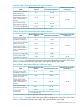
Table 61 (page 155) lists the 10 Gb/s fiber optic cable loss budgets when using OM1, OM2,
OM3, or OM3+ multi-mode fiber optic cable, and single-mode fiber optic cable.
Table 60 (page 155) lists the 16 Gb/s fiber optic cable loss budgets when using OM2, OM3,
OM3+, or OM4 multi-mode fiber optic cable, and single-mode fiber optic cable.
154 SAN fabric connectivity and switch interoperability rules