Part IV SAN extension and bridging SAN extension and bridging are presented in these chapters: • “SAN extension” (page 257) • “iSCSI storage” (page 318) • “Network Attached Storage” (page 365)
18 SAN extension SAN extension enables you to implement disaster-tolerant storage solutions over long distances and multiple sites.
This section describes: • “SAN extension technology” (page 258) • “SAN-iSCSI bridging technology” (page 259) SAN extension technology HP supports the following SAN extension technologies: • • “Fibre Channel long-distance technology” (page 259), including: ◦ “Fiber optic transceivers” (page 259) ◦ “Wavelength division multiplexing” (page 261) ◦ “Extended fabric settings for Fibre Channel switches” (page 264) “Multi-protocol long-distance technology” (page 266), including: ◦ “Fibre Channel over
SAN-iSCSI bridging technology SAN-iSCSI bridging connects Fibre Channel networks and IP networks.
Figure 87 SC GBIC transceiver 25143a Table 131 (page 260) lists supported long-wave transceiver distances and maximum supported distances under ideal operating conditions. Some long-wave optical transceivers can transmit up to a distance of 100 km.
For detailed information about distance rules for long-wave transceivers, see: • “Fibre Channel distance rules for 16 Gb/s and 8 Gb/s switch models (B-series, C-series, and H-series)” (page 157) • “Fibre Channel distance rules for 4 Gb/s switch models (B-series and C-series switches)” (page 158) • “Fibre Channel distance rules for 2 Gb/s switch models (B-series and C-series switches)” (page 159) • “Fibre Channel distance rules for 1 Gb/s switch models (B-series and C-series switches)” (page 159) NOT
WDM system architectures The WDM system architectures are as follows: • Passive (optical transmission protocol) • Active signal amplification • Active protocol handling Most WDM products use one of these architectures or combine attributes of each. Table 132 (page 262) summarizes the WDM system architectures.
• Allow interoperability through standards-compliant interfaces such as Fibre Channel, SONET, and ATM • Convert wavelengths at each interface channel before multiplexing with other channels for transmission HP coarse wave division multiplexing HP offers CWDM, which is similar to DWDM but is less expensive, less expandable (maximum of eight channels), and covers a shorter distance (up to a maximum of 100 km using the 1 Gb/s or 2 Gb/s CWDM SFP transceivers, and a maximum of 40 km using the 4 Gb/s CWDM SFP
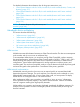
Figure 88 Basic WDM configuration using one long-distance fiber optic link Fabric 1 Local Fabric 1 Remote WDM connection Fabric 2 Local Fabric 2 Remote 25144a The configuration in Figure 88 (page 264) is low cost, but has no long-distance link redundancy.
Table 133 (page 265) describes the appropriate port protocol setting based on the WDM system architecture. Table 133 Port protocol setting based on the extension architecture WDM system architecture B-series port protocol setting Active protocol handling (Table 132 (page 262)) portCfgISLMode slot/port, 1 Passive protocol handling portCfgISLMode slot/port, 0 NOTE: The portCfgISLMode and portCfgLongDistance L0.5, L1, or L2 mode cannot be enabled at the same time; otherwise, fabric segmentation occurs.
H-series switch settings The H-series switches have a fixed BB-credit setting. When using supported long-wave SFP, the following distances are supported: • 3.3 km at 8 Gb/s • 6.6 km at 4 Gb/s • 10 km at 2 Gb/s However, you can use EFMS to allocate more buffer credits to ports of an H-series switch to achieve increased distance up to the limit of the SFP capability, allowing 10 km at 8 Gb/s, 4Gb/s, or 2 Gb/s to be supported.
Figure 90 FCIP single-link configuration Fabric 1 Local Fabric 1 Remote IP 25146a FCIP dual-link configuration A dual-link configuration provides redundancy (Figure 91). If one link fails, the other link temporarily handles all data replication. For enhanced fault tolerance, you can use two IP providers.
Table 135 FCIP network consideration Configuration type Mirrored FCIP SAN Data migration Use existing network? Factors No For peak performance, HP recommends using a separate network. A dedicated network is the benchmark for mirrored FCIP SAN systems. Yes Because data migration is usually a one-time event for upgrade or maintenance purposes, you can use your existing network. However, network performance can be significantly degraded during data migration.
Determining the required bandwidth You can determine the required bandwidth for any application. This example explains how to measure the amount of new or changed data: 1. Collect the peak read and write workloads for a given period of time. For Windows operating systems, use a tool such as PERFMON to capture the current performance requirements while HP P6000 Continuous Access is not running. Similar tools exist for other operating systems. 2.
Table 136 HP FCIP gateways Gateway Supported switches “B-series 1606 Extension SAN Switch and DC Dir Switch MP Extension Blade” (page 287) B-series switches “B-series 400 MP Router and MP Router Blade” (page 290) “B-series MP Router” (page 292) “C-series MDS 9216i, 9222i, IPS-4, IPS-8, 14/2 Multiprotocol Services Modules, 18/4 Multiservice Modules” (page 294) C-series switches “HP IP Distance Gateway (mpx110)” (page 273) B-series, C-series, and H-series switches “MPX200 Multifunction Router with FCIP
FC-SONET IP link configurations Using FC-SONET, you can configure the SANs through a single link, dual links, or shared ISL links. FC-SONET dual-link configuration A dual-link configuration is the benchmark for disaster protection (Figure 93 (page 271)). If one link fails, the other link temporarily handles all data replication. For enhanced fault tolerance, you use two IP providers, accessing the data center through two links.
Fibre Channel over ATM Direct FC-to-ATM conversion is supported by the Fibre Channel standards. However, currently, no vendors sell direct FC-to-ATM gateways. If you have an ATM-based network, consider using FC-to-GbE IP gateways, with an ATM blade residing on the Ethernet switch or IP router to convert the GbE to ATM. For detailed information about distance rules for Fibre Channel over ATM, see “ATM extension Fibre Channel distance rules” (page 160).
Table 138 Features and usage for HP supported FCIP SAN extension products (continued) FCIP gateway Supported product fabrics B-series 1606 Extension SAN Switch DC Dir Switch MP Extension Blade B-series 400 MP Router MP Router Blade Inter-fabric connectivity Supported DR software Data compression method/use Recommended IP bandwidths (WAN) Network requirements VEX_Port B-series See Table 141 (page 287).
IP Distance Gateway configuration examples The IP Distance Gateway supports the configurations shown in Figure 95 (page 274) through Figure 105 (page 280). Figure 95 (page 274) shows a basic FCIP configuration with a local mpx110 and a remote mpx110 connected through an IP WAN using one or two long-distance links.
Figure 97 IP Distance Gateway high-availability configuration with a redundant IP network WAN LAN LAN FCIP GbE Local FC servers GbE Fabric A1 Fabric A2 HP Storage Works mpx100 HP FC1 Storage Works mpx100 Remote FC servers FC1 FC2 FC2 MGMT IOIOI GE1 MGMT IOIOI GE1 GE2 GE2 ! ! mpx110 mpx110 Fabric B1 Fabric B2 HP Storage Works mpx100 HP FC1 Storage Works mpx100 FC1 FC2 FC2 MGMT IOIOI GE1 MGMT IOIOI GE1 GE2 GE2 ! ! mpx110 mpx110 GbE Local storage system LAN GbE
Figure 99 IP Distance Gateway FCIP with B-series Integrated Routing LAN WAN LAN FCIP Local FC servers GbE Fabric A1 EX HP GbE E Storage Works mpx100 HP Storage Works mpx100 FC1 FC1 FC2 FC2 MGMT IOIOI GE1 Fabric A2 Remote FC servers MGMT IOIOI GE1 GE2 GE2 ! ! mpx110 mpx110 Local storage system Remote storage system 26626a Figure 100 (page 276) shows a configuration using the mpx110 with FCIP and C-series switches with IVR.
Figure 101 Highly redundant pairs of gateways, two long distance links LAN WAN LAN FCIP GbE Local FC servers Fabric A1 HP GbE Storage Works mpx100 HP FC1 Remote FC servers Fabric A2 Storage Works mpx100 FC1 FC2 FC2 MGMT IOIOI GE1 MGMT IOIOI GE1 GE2 GE2 GbE ! ! GbE mpx110 Fabric B1 HP mpx110 Storage Works mpx100 HP FC1 Fabric B2 Storage Works mpx100 FC1 FC2 FC2 MGMT IOIOI GE1 MGMT IOIOI GE1 GE2 GE2 ! ! mpx110 Local storage system mpx110 Remote storage system
connectivity and redundancy using six mpx110 gateways. Figure 105 shows the highest level of 3-site connectivity using eight mpx110 gateways. The following configuration rules apply to Figure 103 through Figure 105 (fan-in/fan-out): • For Site 1, Site 2 or Site 3 can function as the remote site. • For Site 2 or Site 3, Site 1 can function as the remote site. • Replication between Site 2 and Site 3 is not supported.
Figure 104 HP P6000 Continuous Access 3-site configuration with six mpx110 gateways LAN HP Fabric A2 Storage Works mpx100 FC1 FC2 MGMT IOIOI GE1 GE2 ! LAN HP mpx110 A2 Fabric B2 Storage Works mpx100 FC1 FC2 MGMT IOIOI GE1 mpx110 B2 GE2 ! Fabric A1 HP LAN Storage Works mpx100 FC1 FC2 MGMT IOIOI GE1 GE2 ! Fabric B1 HP mpx110 A1 Site 2 WAN Storage Works mpx100 FC1 FC2 MGMT IOIOI GE1 GE2 ! mpx110 B1 LAN LAN Site 1 HP Fabric A3 Storage Works mpx100 FC1 FC2 MGMT IOI
Figure 105 HP P6000 Continuous Access 3-site configuration with eight gateways LAN LAN HP Fabric A2 Storage Works mpx100 FC1 FC2 MGMT IOIOI GE1 mpx110 A2 GE2 ! Fabric A1 HP Storage Works mpx100 FC1 FC2 MGMT IOIOI GE1 GE2 ! mpx110 A1-1 HP Fabric B2 Storage Works mpx100 FC1 FC2 MGMT IOIOI GE1 mpx110 B2 GE2 ! HP Storage Works mpx100 FC1 FC2 MGMT IOIOI GE1 GE2 ! mpx110 A1-2 LAN LAN Site 2 WAN LAN LAN HP Storage Works mpx100 FC1 FC2 MGMT IOIOI GE1 GE2 ! mpx110 B1-1 H
Figure 106 (page 281) shows long-distance link redundancy and full connectivity between all three sites.
For current storage system support, see the SPOCK website at http://www.hp.com/storage/spock. You must sign up for an HP Passport to enable access. Operating system and multipath support The mpx110 gateway is supported using FCIP with all operating systems and multipath software supported by HP for HP P6000 Continuous Access, HP P9000 (XP) Continuous Access, and 3PAR Remote Copy. See Table 139 (page 273) and Table 140 (page 283).
The MPX200 FCIP feature can be configured as a standalone function or for use simultaneously with iSCSI. A license is required to enable the FCIP feature. All licenses are half-chassis based, enabling FCIP to be configured on one or both bays (slots) in a dual-blade chassis configuration.
Figure 107 MPX200 basic FCIP configuration with one or two long-distance links LAN WAN LAN FCIP Local FC servers Fabric A1 GbE GbE GbE HP HP Fabric A2 GbE Remote FC servers Storage Works MPX200 Storage Works MPX200 GE4 GE4 GE3 MGMT GE3 MGMT IOIOI IOIOI MPX200 MPX200 1 GbE Multifuncti Blade on Router 1 GbE Multifuncti Blade on Router FC1 FC1 FC2 FC2 GE1 GE1 GE2 GE2 MPX200 MPX200 Fabric B1 Fabric B2 Local storage system Remote storage system 26609b Figure 108 (page 284) shows
Figure 109 (page 285) shows a configuration using the MPX200 with FCIP and C-series switches with IVR. This provides fabric isolation between the local and remote fabrics, allowing device access without merging the fabrics. This can be implemented in all supported MPX200 FCIP configurations using C-series Fibre Channel switches with IVR.
Figure 111 Local MPX200 basic FCIP configuration with remote IP Distance Gateway (mpx100) LAN WAN LAN FCIP Local FC servers Fabric A1 GbE HP GbE GbE Fabric A2 mpx110 Fabric B2 GbE Remote FC servers Storage Works MPX200 HP GE4 GE3 MGMT Storage Works mpx100 FC1 IOIOI MPX200 FC2 1 GbE Multifuncti Blade on Router MGMT FC1 IOIOI GE1 GE2 FC2 ! GE1 GE2 Fabric B1 MPX200 Local storage system Remote storage system 26611b FCIP Configuration rules The section describes the FCIP configu
For XP, the MPX200 is supported for use with HP P9000 (XP) Continuous Access for XP24000/20000 and XP12000/10000. • The MPX200 Multifunction Router is supported for use in all supported HP P6000 Continuous Access SAN configurations, including the standard two-fabric, five-fabric, and six-fabric configurations. For more information, see the HP P6000 Continuous Access documentation. • FCIP is supported for HP P6000 Continuous Access DR group LUNs and non-DR LUNs.
Table 141 1606 Extension SAN Switch and DC Dir Switch MP Extension Blade features and requirements (continued) Feature Requirements These products are also supported for use as Fibre Channel switches. This provides both Fibre Channel switch connectivity for hosts and storage systems and FCIP connectivity for SAN extension.
Figure 112 NSPOF configuration with 1606 Extension SAN Switches providing Fibre Channel routing and FCIP 1606 Extension SAN Switch 1606 Extension SAN Switch Fabric A1 Fabric A2 IP A FCIP with FC routing 1606 Extension SAN Switch Fabric B1 1606 Extension SAN Switch Fabric B2 IP B FCIP with FC routing 26583b Figure 113 Fibre Channel routing and FCIP using two 1606 Extension SAN Switches Fabric A1 1606 Extension SAN Switch IP A 1606 Extension SAN Switch Fabric A2 IP B Fabric B1 Fabric B2 FCIP w
B-series 400 MP Router and MP Router Blade The B-series 400 MP Router and MP Router Blade offer FCIP SAN extension, Fibre Channel routing, and Fibre Channel switching. You can use all three of these functions on the same 400 MP Router or MP Router Blade simultaneously. A 400 MP Router or MP Router Blade can have: • Up to 2 GbE IP ports for FCIP. For more information, see “SAN extension” (page 257). • Up to 16 EX_Ports for Fibre Channel routing services.
Table 142 400 MP Router and MP Router Blade features and requirements (continued) Feature Requirements • HP P6000 Continuous Access • HP P9000 (XP) Continuous Access • HP 3PAR Remote Copy For operating system support, see “Heterogeneous server rules” (page 165). FCIP FastWrite is supported with HP P9000 (XP) Continuous Access and is not supported with HP P6000 Continuous Access.
HP supports FCIP configurations in which the 400 MP Router or MP Router Blade serves as an FCIP gateway and a Fibre Channel switch. Servers and storage systems that support Continuous Access with FCIP can be directly connected to the Fibre Channel ports on the 400 MP Router or MP Router Blade (Figure 117).
Table 143 B-series MP Router features and requirements Feature Requirements The MP Router is supported with the B-series switches listed in “B-series switches and fabric rules” (page 91). The MP Router is not supported for use as a Fibre Channel switch. Direct device connectivity to MP Router ports (F_Ports) is supported only with iSCSISee “iSCSI storage” (page 318).
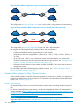
Figure 119 MP Routers connecting fabrics using two IP subnets MPR 2 Fabric 2 MPR 1 IP subnet A Fabric 1 IP subnet B MPR 3 Fabric 3 25153a In this sample configuration, MP Router 1 must have a GbE connection to IP subnet A and a GbE connection to a IP subnet B. A Fibre Channel host or device connected to Fabric 1 can access devices in Fabric 2 and/or Fabric 3. Figure 120 (page 294) shows a redundant FCIP configuration in which pairs of MP Routers provide full redundancy.
Table 144 (page 295) lists the features and requirements for the C-series modules.
The following sections describe network requirements for replication products with qualified gateways: • “SAN extension best practices for HP P6000 Continuous Access” (page 296) • “ HP P6000 Continuous Access with XCS 11x, XCS 10x, or XCS 09x” (page 296) • “HP P6000 Continuous Access with XCS 6.x” (page 298) • “HP P6000 Continuous Access with VCS 4.
Table 145 Network requirements for long-distance IP gateways with XCS 11x, XCS 10x, or XCS 09x Specification Description • Must be dedicated to the HP P6000 Continuous Access storage replication function. IP bandwidth1 • The minimum IP bandwidth required for HP P6000 Continuous Access with P63xx/P65xx EVA, EVA4400/6400/8400, and EVA4400 (embedded switch) with FCIP is 2 Mb/s per path, or 4 Mb/s for two paths when using one IP link. • There is no support for dynamic pacing of the gateway.
Table 146 Network requirements for long-distance IP gateways and B-series switches with XCS 11x, XCS 10x, or XCS 09x Minimum IP bandwidth1and maximum DR groups2 Gateway pair HP IP Distance Gateway (mpx110) Minimum supported firmware version DC Dir Switch MP Extension Blade B-series 400 MP Router Single or shared IP link maximum latency 0 to 100 ms one-way 0 to 100 ms one-way See note.
pairs. Table 148 (page 299) lists the network requirements for long-distance gateways that work with EVA XCS 6.x. Table 148 Network requirements for long-distance IP gateways with XCS 6.x Specification Description • Must be dedicated to the HP P6000 Continuous Access storage replication function. IP bandwidth1 • The minimum IP bandwidth required for HP P6000 Continuous Access with FCIP is 2 Mb/s per path, or 4 Mb/s for two paths when using one IP link.
Table 149 Network requirements for long-distance IP gateways and B-series switches with XCS 6.x Minimum IP bandwidth1and maximum DR groups2 Minimum supported Gateway pair firmware version HP IP Distance Gateway (mpx110) Dual IP link maximum latency Single or shared IP link maximum latency 0 to 100 ms one-way 0 to 100 ms one-way See note.
Table 150 (page 301) describes the network bandwidth requirements and IP gateway support for XCS 6.x with C-series switches. Table 150 Network requirements for long-distance IP gateways and C-series switches with XCS 6.x Minimum IP bandwidth1and maximum DR groups2 Minimum supported Gateway pair firmware version HP IP Distance Gateway (mpx110) Dual IP link maximum latency Single or shared IP link maximum latency 0 to 100 ms one-way 0 to 100 ms one-way See note.
Table 151 Network requirements for long-distance IP gateways with VCS 4.x (continued) Specification Description High-loss network: 0.2% average over 24 hours; must not exceed 0.5% for more than 5 minutes in a two-hour window Latency jitter3 Must not exceed 10 ms over 24 hours 1 Pre-existing restriction 2 A high packet-loss ratio indicates the need to retransmit data across the inter-site link.
Table 152 (page 303) describes the network bandwidth requirements and IP gateway support for VCS 4.x with B-series switches. Table 152 Network requirements for long-distance IP gateways and B-series switches with VCS 4.x Minimum IP bandwidth1and maximum DR groups2 Gateway pair HP IP Distance Gateway (mpx110) Minimum supported firmware version Dual IP link maximum latency Single or shared IP link maximum latency 0 to 100 ms one-way 0 to 100 ms one-way See note.
Table 153 (page 304) describes the network bandwidth requirements and IP gateway support for VCS 4.x with C-series switches. Table 153 Network requirements for long-distance IP gateways and C-series switches with VCS 4.x Minimum IP bandwidth1 and maximum DR groups2 Gateway pair HP IP Distance Gateway (mpx110) Minimum supported firmware version Dual IP link maximum latency Single or shared IP link maximum latency 0 to 100 ms one-way 0 to 100 ms one-way See note.
Table 154 HP P9000 (XP) Continuous Access replication modes1 Storage system P95004 XP24000 XP20000 XP12000 XP10000 Synchronous Asynchronous2 Journal3 Recommended firmware versions Minimum firmware versions • — • V01 V01+1 • • • 60.06.05.00/00 60.01.68.00/00 • • • 50.09.86.00/005 50.05.46.00/005 1 Legend: • = supported; — = not supported 2 XP24000/20000/12000/10000: 32K pairs 3 XP24000 with RAID Manager 1.20.05 (or later), XP12000/10000 with RAID Manager 1.17.
Table 156 HP P9000 (XP) Continuous Access Synchronous replication rules (continued) Rule number Description dark fiber, or less than 5 ms using other extension methods. Distances greater than 200 km or latencies greater than 5 ms require HP approval before implementation. Contact HP product support if using greater distances or latencies.
Table 158 HP P9000 (XP) Continuous Access Journal replication rules (continued) Rule number Description 50.08.05.00/00 (or later) allows creation of Business Copy from these devices, but does not allow a fast-restore operation for a Business Copy device. 9 A P-vol can support a maximum of two remote copies (one Continuous Access Journal copy and one Continuous Access Synchronous copy).
• Direct storage-to-storage • Fibre Channel switches • ESCON directors and repeaters • WDM • ATM and SONET/SDH • FCIP and routing extension Direct storage-to-storage Figure 124 (page 308) shows an HP P9000 (XP) Continuous Access direct storage-to-storage configurations for Fibre Channel and ESCON. Table 159 (page 308) describes the maximum supported distances.
Figure 125 HP P9000 (XP) Continuous Access single-switch and multi-switch Fibre Channel configurations RCU I I RCU RCU I I RCU Local Remote 25327a Table 160 HP P9000 (XP) Continuous Access Fibre Channel distances Configuration Maximum distance Single-switch or multi-switchSee Figure 125 (page 309). Note: For Fibre Channel switch model support, contact an HP storage representative.
Figure 127 HP P9000 (XP) Continuous Access ESCON repeater configuration RCP MME SME LCP SME SME MME LCP MME RCP SME MME Local Remote ESCON repeater/director 25326a Table 161 HP P9000 (XP) Continuous Access ESCON director and repeater distances Configuration Maximum distance IBM 9032/9033 director 3 km for short-wave, multi-mode ESCON (MME) IBM 9036 repeater 20 km for long-wave, single-mode ESCON (SME) Nbase Xyplex Note: Supported only in a director-to-director configuration.
Table 162 HP P9000 (XP) Continuous Access WDM distances and equipment (continued) Configuration Maximum distance and equipment Nortel Optera Metro 5200/5100 Movaz RAYexpress ATM and SONET/SDH Figure 129 (page 311) shows HP P9000 (XP) Continuous Access ATM and SONET/SDH configurations. Table 163 (page 312) describes the supported products.
Table 163 HP P9000 (XP) Continuous Access ATM and SONET/SDH products1 XP storage system Configuration ESCON (ATM) XP24000 XP20000 Supported bandwidths and products OC-3—Brocade-CNT Ultranet Storage Director (USD) firmware 2.7 or 3.2.1 OC-3—Brocade-CNT-Inrange 9801 SNS firmware 2.3 (Build 27) or 2.4 (Build 13) Brocade-CNT-Inrange 9811H FW ACP-3; 3.1.
Figure 131 (page 313) and Figure 132 (page 313) show HP P9000 (XP) Continuous Access FCIP and iFCP configurations.
Table 164 Network requirements for long-distance IP gateways with HP P9000 (XP) Continuous Access (continued) Specification Maximum latency1 Requirement See Table 156 (page 305), Table 157 (page 306), and Table 158 (page 306). Low-loss network: 0.0012% average over 24 hours Average packet-loss ratio2 High-loss network: 0.2% average over 24 hours; must not exceed 0.
Table 165 HP P9000 (XP) Continuous Access FCIP gateway support (continued) Product and minimum supported firmware version Table 21 (page 94). XP storage system XP10000 Notes ◦ aptpolicy = 1 ◦ aptpolicy –ap = 0 (port/asic load sharing) ◦ dlsReset (no dynamic load sharing) Exchange-based routing: ◦ aptpolicy = 3 ◦ aptpolicy –ap = 0 (port/asic load sharing) ◦ dlsSet (dynamic load sharing) For additional requirements, see Table 141 (page 287) and Table 160 (page 309).
1 For current support, see the SPOCK website at http://www.hp.com/storage/spock. You must sign up for an HP Passport to enable access. Table 166 HP P9000 (XP) Continuous Access iFCP gateway support Product and minimum supported firmware version XP storage system Brocade-CNT Edge 3000 Firmware: 3.1.1.3, 3.1.2, 3.1.4, 3.1.
Certified third-party WDM, iFCP, and SONET products This section describes the following topics: • “Certified third-party WDM products” (page 317) Certified third-party WDM products HP supports HP P6000 Continuous Access, HP P9000 (XP) Continuous Access, 3PAR Remote Copy, and SVSP Synchronous Mirrors (RAID1) on all WDM products, including DWDM and CWDM, certified by the Fibre Channel switch vendors for the equivalent HP switch models.
19 iSCSI storage This chapter describes iSCSI storage in an HP SAN environment: • “iSCSI overview” (page 318) • “iSCSI concepts” (page 318) • “iSCSI storage network requirements” (page 322) • “HP Native iSCSI products” (page 322) • “HP iSCSI bridge products” (page 332) iSCSI overview iSCSI is a storage transport protocol. The IETF developed iSCSI to encapsulate the SCSI protocol over an IP network. iSCSI has many of the same mechanisms as the Parallel SCSI and Fibre Channel protocols.
• “Software and hardware iSCSI initiators” (page 321) • “Bridging and routing” (page 332) • “iSCSI boot” (page 321) Initiator and target devices An iSCSI router manages access between iSCSI targets and iSCSI initiators as follows: • iSCSI target (logical target)—An end-node device that is typically a storage system, storage router, or bridge. A storage system with iSCSI support is called native iSCSI storage.
Service Location Protocol Clients (initiators) discover services (targets) using SLP, a client-server protocol. SLP for iSCSI uses three components: • An iSCSI initiator has an SLP UA that serves as a client. • iSCSI targets have an SLP SA that acts as an SLP server. • A DA interprets multicast service requests from the server.
During iSCSI login, the initiator and target negotiate the lowest mutually acceptable value for each parameter. Negotiable parameters include: • Type of security protocol, if any • Maximum size of the data payload • Support for unsolicited data • Time-out values During iSCSI login, the initiator and target also exchange nonnegotiable values such as names and aliases. During an iSCSI session, unique session IDs are created for the initiator and target: 1.
iSCSI storage network requirements HP recommends: • Dedicated IP network for iSCSI storage (can be required for some iSCSI products) • Minimum GbE network bandwidth • Multipathing driver when implementing high availability See the iSCSI product sections for additional requirements: • “HP StoreVirtual Storage” (page 329) • “MPX200 Multifunction Router with iSCSI for P6000/EVA storage” (page 333) • “EVA and EVA4400 iSCSI Connectivity Option ” (page 344) • “B-series MP Router and iSCSI” (page 355)
Table 169 10 GbE iSCSI operating system and multipath software support Operating system Multipath software Clusters Microsoft Windows Server 2008, 2003 3PAR MPIO (Windows 2003) MSCS (Windows 2003) Microsoft MPIO DSM (Windows 2008) Failover Cluster (Windows 2008) Red Hat Linux, SUSE Linux, Citrix XenServer Device Mapper Red Hat native cluster suite Solaris Solaris MPxIO Native Solaris cluster VMware VMware MPxIO Native ESX/ESXi cluster solution Citrix XenServer native cluster suite All host
Table 171 iSCSI operating system and multipath software support Operating system Multipath software Clusters Microsoft Windows Server 2008, 2003 3PAR MPIO (Windows 2003) MSCS (Windows 2003) Microsoft MPIO DSM (Windows 2008) Failover Cluster (Windows 2008) Red Hat Linux, SUSE Linux, Citrix XenServer Device Mapper Red Hat native cluster suite Solaris Solaris MPxIO Native Solaris cluster VMware VMware MPxIO Native ESX/ESXi cluster solution Citrix XenServer native cluster suite All hosts must
Table 172 iSCSI/FCoE operating system and multipath software support Operating system Multipath software Clusters Apple Mac OS X (1GbE iSCSI only) None None Microsoft Windows Server 2008, 2003 MPIO with HP DSMMPIO with Microsoft DSM (with CN1000E only) Failover Clustering, MSCS Hyper-V (1 GbE iSCSI only) Red Hat Linux, SUSE Linux Device Mapper None Solaris (1 GbE iSCSI only) Solaris MPxIO None VMware VMware MPxIO None For more information, see the iSCSI or iSCSI/FCoE configuration rules an
MSA2000i G2 and MSA2000i overview The HP StorageWorks Modular Smart Array 2000i G2 (MSA2300i G2) and the HP StorageWorks Modular Smart Array 2000i (MSA2000i) are controller shelves with an iSCSI interface that serves as an iSCSI target.
Table 174 MSA iSCSI storage family maximum configurations (continued) Model Array chassis Expansion1 Expansion maximum 2024 2.5-in drive bay (SFF, upgrade only) MSA2000i G2 2012 3.5-in drive bay (LFF) MSA2000 LFF drive enclosure 5 total enclosures or 99 drives 60 LFF drives MSA2300i 2024 2.5-in drive bay (SFF) MSA2012i Preconfigured single or 4 total enclosures dual controller 3.
Operating system support Table 175 (page 328) lists the supported operating systems for the MSA iSCSI storage family.
Maximum configurations Table 176 (page 329) lists the maximum configurations for the MSA iSCSI storage family. Table 176 MSA iSCSI storage family maximum configurations Storage systems Operating systems Drives LUNs 64 512 Up to 64 TB, 64 standard depending on (maximum 512 vdisk snapshots) configuration 512 Up to 64 TB, 64 standard depending on (maximum 512 vdisk snapshots) configuration Microsoft Windows MSA 2040 SAN Red Hat Enterprise Linux SUSE Linux Enterprise Server 96 3.5-in LFF 199 2.
volume in the cluster. With multiple iSCSI network interfaces across the cluster, a virtual IP address across these interfaces presents the volumes as targets to iSCSI initiators. Key features include: • A cluster of pooled storage supporting up to 16 storage nodes. For larger configurations, contact an HP storage representative. • Two 1GbE ports per storage node (or optional upgrade to SPF+ 10GbE dual ports per storage node).
• Citrix/Linux/Unix bonding of network interfaces performed at the networking layer • For more information, see the following documents: ◦ HP StoreVirtual 4000 Storage Application Aware Snapshot Manager Deployment Guide, at www.hp.com/go/P4000Support (in the Manuals section) ◦ HP StoreVirtual 4000 Storage with VMware vSphere: Design considerations and best practices, at h20195.www2.hp.com/v2/GetDocument.
Table 177 Configuration recommendations Storage item Best practice Caution Not recommended Status indicator Green Orange Red 1 to 1,000 1,001 to 1,500 1,501+ 1 to 4,000 4,001 to 5,000 5,001+ Nodes per group 1 to 20 21 to 32 33+ Nodes per cluster 1 to 10 11 to 15 16+ Volumes + Snapshots + SmartClones iSCSI sessions per group LUN size The maximum LUN size for a fully provisioned volume depends on the storage node size, local RAID configuration, and network RAID configuration settings f
• EVA iSCSI Connectivity Option • EVA4400 iSCSI Connectivity Option MPX200 Multifunction Router with iSCSI for P6000/EVA storage The P6000/EVA family of FC storage systems supports integrated iSCSI connectivity using the MPX200 Multifunction Router.
Figure 135 (page 334) shows an MPX200-EVA dual-blade fabric-attached configuration. This configuration provides high availability with failover between blades.
Figure 137 MPX200 dual-blade multi-EVA configuration MGMT HP StorageWorks MPX200 MGMT MPX200 blade 1 GE4 IOIOI GE3 FC1 FC2 FC1 HP StorageWorks MPX200 GE1 FC2 MPX200 blade 2 MGMT 1 GbE Blade MPX200 Multifunction Router GE4 IOIOI MGMT GE2 IP network management (WAN/LAN) GE3 1 GbE Blade MPX200 Multifunction Router FC1 FC2 FC1 GE1 GE1 FC2 IP network iSCSI data (LAN/VLAN) GE2 GE1 iSCSI NIC P6000 Command View P6000/EVA storage system FP1 FP2 FP1 FP2 FP1 FP2 FP1 FP2 FP1 FP
Figure 139 MPX200 single-blade direct connect to one EVA configuration IP network management (WAN/LAN) MPX200 MGMT HP StorageWorks MPX200 GE4 IOIOI MGMT GE3 1 GbE Blade MPX200 Multifunction Router FC1 FC2 FC1 GE1 FC2 GE2 iSCSI GE1 IP network iSCSI data (LAN/VLAN) NIC P6000/EVA storage system FP1 FP2 FP1 FP2 A B 26640a Figure 140 MPX200 dual-blade direct connect to two EVA configuration MPX200 blade 1 MGMT HP StorageWorks MPX200 MGMT GE4 IOIOI GE3 FC1 FC2 FC1 HP StorageWorks
Table 178 Supported MPX200 maximums (continued) Maximum per MPX200 solution1 Description Total number of iSCSI LUNs 4,096 per chassis, 1,024 per EVA or XP iSCSI connections, 1-GbE 1,024 per blade, 2,048 per chassis iSCSI connections, 10-GbE 2,048 per blade, 4,096 per chassis 1 For mixed blade type chassis configurations that include one 1-GbE blade and one 10-GbE blade, the maximum values for a 1-GbE blade prevail.
All MPX200 configurations must follow these P6000/EVA connectivity rules: • When using the MPX200 for iSCSI, MPX200 FC connections can be direct connect to a P6000/EVA controller host port or fabric connect through an FC switch. • Each P6000/EVA storage system can connect to a maximum of one MPX200 chassis (two blades). • Each P6000/EVA controller host port can connect to a maximum of two MPX200 FC ports.
NOTE: Communication between HP P6000 Command View and the MPX200 is not secured by the communication protocol. If this unsecured communication is a concern, HP recommends a confined or secured IP network within a data center. P6000/EVA storage system software For FCIP, the MPX200 is supported with HP P6000 Continuous Access, Business Copy, SSSU, or Replication Solutions Manager.
Figure 141 (page 340) shows an MPX200-3PAR single-blade fabric-attached configuration. This is the lowest-cost configuration and is used when high availability for iSCSI hosts is not required.
Figure 143 MPX200-3PAR multi-3PAR fabric-attached configuration IP network management (WAN/LAN) MPX200 MGMT HP StorageWorks MPX200 MGMT GE4 IOIOI GE3 FC1 1 GbE Blade MPX200 Multifunction Router FC2 FC1 GE1 FC2 GE2 GE1 IP network iSCSI data (LAN/VLAN) iSCSI NIC 3PAR storage system Fibre Channel fabric 2 Fibre Channel fabric 1 26666a MPX200 iSCSI rules and supported maximums The MPX200 chassis can be configured with one or two blades.
Table 182 MPX200-3PAR StoreServ operating system and multipath support Operating system Multipath software Citrix Xen 3PAR storage system Native MPxIO Microsoft Windows Server 2012, 2008, 2003 3PAR MPIO (Windows 2003) Microsoft MPIO DSM (Windows 2012, 2008) Oracle VM Server Native Device Mapper Linux Red Hat, SUSE Device Mapper Oracle Solaris Solaris MPxIO 3PAR StoreServ 10000 V-Class; 3PAR StoreServ 7000; 3PAR F-Class, T-Class MPX200 Multifunction Router with iSCSI for XP storage The XP24000/
Figure 145 MPX200-XP dual-blade fabric-attached configuration MPX200 blade 1 MGMT HP StorageWorks MPX200 MGMT GE4 IOIOI GE3 FC1 MGMT HP StorageWorks MPX200 1 GbE Blade MPX200 Multifunction Router FC2 FC1 GE1 FC2 GE2 MGMT GE4 IOIOI GE3 FC1 1 GbE Blade MPX200 Multifunction Router FC2 FC1 GE1 IP network management (WAN/LAN) MPX200 blade 2 GE1 FC2 GE2 iSCSI GE1 IP network iSCSI data (LAN/VLAN) XP24000/20000 storage system NIC Fibre Channel fabric 1 Fibre Channel fabric 2 26655a
• XP24000 • XP20000 All MPX200 configurations must follow these connectivity rules: • When using the MPX200 for iSCSI, MPX200 FC connections must be fabric-attached through an FC switch • Each XP storage system can connect to a maximum of one MPX200 chassis (two blades) • A maximum of one MPX200 chassis (two blades) can be zoned with up to four XP storage systems • XP and EVA storage systems can connect to the same MPX200, the total allowable number of storage systems is four per MPX200 chassis •
Figure 147 Direct connect iSCSI-Fibre Channel attachment mode configuration Discovery IP Address Presented iSCSI Targets D1 FP1B mpx100 HP StorageWorks mpx100 FP1A IP Network management (WAN/LAN) MGMT MGMT IOIOI ! FC1 FC1 FC2 FC2 GE1 GE2 GE1 IP Network iSCSI data (LAN/VLAN) D1 EVA storage system FP1 FP2 FP1 FP2 Existing Fibre Channel HA fabric 1 A B iSCSI NIC P6000 Command View Existing Fibre Channel HA fabric 2 25162c NOTE: Direct connect mode requires a dedicated host port on
Figure 149 EVA4400 direct connect iSCSI-Fibre Channel attachment mode ABM configuration Discovery IP Address Presented iSCSI Targets D1 FP2A FP2B FP2A D2 FP2B FP1A FP1B FP1A FP1B D3 D4 IP Network management (WAN/LAN) mpx100/100b 1 mpx100/100b 2 MGMT MGMT HP StorageWorks mpx100 HP StorageWorks mpx100 MGMT IOIOI MGMT IOIOI ! FC1 FC1 FC2 GE1 ! GE2 GE1 FC2 FC1 GE2 FC1 FC2 FC2 GE1 GE2 GE1 GE2 D2 D1 D4 D3 iSCSI IP Network iSCSI data (LAN/VLAN) NIC EVA4400 with ABM running P60
Figure 151 Fabric iSCSI-Fibre Channel attachment mode configuration Discovery IP Address Presented iSCSI Targets D1 FP2A IP Network management (WAN/LAN) FP2B mpx100 FP1A HP StorageWorks mpx100 FP1B MGMT MGMT IOIOI ! FC1 FC1 FC2 FC2 GE1 GE2 GE1 D1 EVA storage system FP1 FP2 FP1 FP2 IP Network iSCSI data (LAN/VLAN) Existing Fibre Channel HA fabric 1 A B iSCSI NIC P6000 Command View Existing Fibre Channel HA fabric 2 25164c Hardware support This section describes the hardware devi
Table 184 (page 348) describes the connectivity attachment mode based on the EVA storage system model.
See Figure 152 (page 349) and Figure 153 (page 349). NOTE: HP Storage mpx Manager is required for mpx100/100b management.
Figure 154 Multipath direct connect iSCSI-Fibre Channel attachment mode configuration Discovery IP Address Presented iSCSI Targets D1 FP1A D2 FP1B IP Network management (WAN/LAN) mpx100/100b 1* mpx100/100b 2 MGMT MGMT HP StorageWorks mpx100 HP StorageWorks mpx100 MGMT IOIOI MGMT IOIOI ! FC1 FC1 FC2 GE1 ! GE2 GE1 FC2 FC1 GE2 FC1 FC2 FC2 GE2 GE1 GE1 GE2 IP Network iSCSI data (LAN/VLAN) D1 D2 EVA storage system FP1 FP2 FP1 FP2 Existing Fibre Channel HA fabric 1 A B iSC
Operating systems and network interface cards The EVA and EVA4400 iSCSI options support the following operating systems, unless noted otherwise: • Apple Mac OS X • Linux—Red Hat • Linux—SUSE • Microsoft Windows 2008 Enterprise/Standard Editions; 2008 Server Core; 2003 Enterprise/Standard Editions • Microsoft Windows XP Professional Workstation • HP OpenVMS 8.
Table 185 Supported EVA iSCSI Connectivity Option maximums Description Maximum per EVA or EVA4400 iSCSI Connectivity Option Hardware EVA storage system 1 mpx100/100b 2 Configuration mpx100—150 (single-path or multipath) mpx100b (EVA4400 only)—16, 48 (license upgrade 1), 150 (license upgrade 2) (single-path or multipath) Total number of iSCSI initiators Note: The mpx100/100b can serve both single-path and multipath LUNs concurrently.
B-series iSCSI Director Blade The B-series iSCSI Director Blade (FC4-16IP) is a gateway device between Fibre Channel targets and iSCSI initiators. This allows iSCSI initiators in an IP SAN to access Fibre Channel storage in a Fibre Channel SAN. This section describes the following topics: • “Blade overview” (page 353) • “Hardware support” (page 353) • “Software support” (page 354) • “Scalability rules” (page 354) For the latest B-series documentation, see http://h18006.www1.hp.
Storage systems The following storage system is supported with the B-series iSCSI Director Blade. Contact an HP storage representative for specific support information. • XP10000/12000 NOTE: HP supports direct connection of storage systems to the Fibre Channel ports on the B-series iSCSI Director Blade, not to the IP ports. Fibre Channel switches The B-series iSCSI Director Blade is supported on the B-series SAN Director 4/256, with a maximum of four blades per chassis.
Table 187 B-series iSCSI Director Blade scalability rules Rule iSCSI sessions per port 64 Maximum 64 iSCSI ports per FC4–16IP blade 8 iSCSI blades per switch 4 iSCSI sessions per FC4–16IP blade 512 iSCSI sessions per switch 1,024 TCP connections per switch 1,024 TCP connections per iSCSI session 2 iSCSI sessions per fabric 4,096 TCP connections per fabric 4,096 iSCSI targets per fabric 4,096 CHAP entries per fabric 4,096 LUNs per iSCSI target 256 Members per discovery domain 64 Dis
Operating systems and network interface controllers The MP Router supports the following operating systems: • Microsoft Windows 2000 SP3, SP4 • Microsoft Windows 2003 Standard Server and Enterprise Editions The MP Router in iSCSI mode is compatible with all HP-supported NICs for Windows. Network Teaming MP Router iSCSI supports HP Network Teaming with Windows 2000 and Windows 2003. iSCSI initiators MP Router iSCSI supports Microsoft iSCSI initiator 1.06.
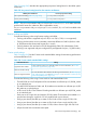
Figure 157 (page 357) shows a sample configuration where an IP module bridges an IP network and a Fibre Channel network. Figure 157 C-series Fibre Channel and IP configuration with the IP module Fibre Channel IP link ISL C-series Fibre Channel with IPS module Host 1 Host 2 IP network Fibre Channel C-series fabric Fibre Channel 25167c In addition to presenting Fibre Channel targets to iSCSI hosts, the modules also present each iSCSI host as a Fibre Channel host (in transparent mode).
Fibre Channel switches The C-series IP Storage Services Modules (IPS-4, IPS-8), 14/2 Multiprotocol Services Module, and 18/4 Multiservice Module support the HP C-series switches listed in “C-series switches and fabric rules” (page 123). Table 189 (page 358) describes the C-series switches that support iSCSI.
C-series management applications C-series management applications are as follows: • Cisco Data Center Network Manager (DCNM) • Cisco Fabric Manager • Cisco Device Manager • CLI iSCSI initiators C-series modules support these iSCSI software initiators: • Microsoft Windows iSCSI Initiator • Red Hat iSCSI bundled Initiator • Red Hat SourceForge iSCSI Initiator • SUSE iSCSI bundled Initiator • SUSE SourceForge iSCSI Initiator • IBM AIX native iSCSI Initiator • Oracle Solaris native iSCSI In
The following examples show maximum configurations for initiator/target pairs: • 500 iSCSI initiators, each connecting to one target (storage controller port) • 100 iSCSI initiators, each connecting to five targets • 50 iSCSI initiators, each connecting to eight targets and 100 iSCSI initiators, each connecting to one target The maximum of 500 TCP connections (initiator/target pairs) with 256 LUNs per connection yields 128,000 possible LUNs.
• HP ProLiant DL380 G4 Storage Server (Base, External SCSI, and External SATA models, SAN Storage model Gateway Edition only) • HP StorageWorks NAS 500s • HP StorageWorks NAS 1200s • HP StorageWorks NAS 1500s • HP StorageWorks NAS 2000s • HP StorageWorks NAS 4000s (Gateway Edition only) Application support The following host applications support the HP iSCSI Feature Pack: • Microsoft Exchange Server 2000 • Microsoft Exchange Server 2003 • Microsoft SQL Server 2000 • Microsoft SQL Server 2
• Allows delta snapshots using Microsoft VSS interface, and performs automatic delta snapshots of application hosts to reduce potential data loss. • Offers several application-specific licensed agent options: ◦ Microsoft Visual SourceSafe ◦ Microsoft Exchange ◦ Microsoft SQL ◦ Oracle Database (for a single Microsoft iSCSI initiator) Clustering Clustering is an upgrade license for the HP ProLiant Storage Server iSCSI Feature Pack (Gateway Edition only).
Exchange storage design Important criteria for Exchange storage design include: • Isolation of Exchange transaction logs from databases • Selection of optimum RAID level for performance and fault tolerance • Write-back caching for hardware RAID controller performance Separate volumes for logs and databases HP recommends separate volumes for Exchange transaction logs and databases, to ensure data protection and efficiency.
calculated from the average I/O needs an additional safety factor to maintain performance during peak periods. In practice, the maximum number of users is less than the calculated value when: • Users increase the size of their mailboxes. • Services such as antivirus scanners or content indexers are added to the Exchange server. A medium-sized user profile provides a 60 MB mailbox, and a large profile provides a 100 MB mailbox.
20 Network Attached Storage This chapter describes the HP ProLiant Storage Server family of NAS products. It describes the following topics: • “Storage server and SAN integration” (page 365) • “HP ProLiant Storage Servers” (page 366) NOTE: The HP ProLiant Storage Server family was formerly called the HP StorageWorks NAS family. Legacy NAS products use the HP StorageWorks NAS brand. For information about iSCSI NAS configurations, see “HP ProLiant Storage Server iSCSI Feature Pack support” (page 360).
HP ProLiant Storage Servers The HP ProLiant Storage Servers provide scalability, flexibility, and cost-effective management of storage resources. HP offers the following storage servers: • HP ProLiant DL380 G4 • HP ProLiant DL580 G2 • HP ProLiant DL585 NOTE: The DL380 G4 was formerly called NAS 4000s; the DL580 G2 was called NAS 9000s.
For additional information, see the following QuickSpecs: • DL380 G4: http://h18006.www1.hp.com/products/storageworks/dl380storageserver/ index.html • DL580 G2: http://h18006.www1.hp.com/products/storageworks/dl580storageserver/ specifications.html • DL585: http://h18006.www1.hp.com/products/quickspecs/11902_na/11902_na.html Fabric rules Storage servers are supported in SAN fabrics with B-series or C-series switches.