
HP 9000 rp8420 Server - User Service Guide, Fifth Edition
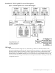
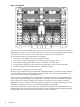
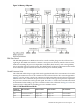
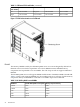
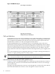
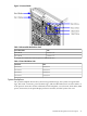

Figure 1-10 System Backplane Block Diagram
The LBA PCI bus controllers are placed on the system backplane to facilitate removal of the core
I/O cards when standby power is applied. The partition for the core I/O card must be shut down
before removing the card.
Having the SCSI connectors on the system backplane allows removal of the core I/O card without
having to remove cables in the process. Hot-plug circuitry is located near the system
backplane/core I/O card mating area.
System Backplane to Cell Board Connectivity
Four sets of vertical connectors serve as the point of connection for the cell boards. In addition,
two vertical connectors per cell board carry signals from the CC on the cell board to the SBA
chip on the PCI-X backplane, or an external I/O chassis PCI-X backplane, and back through the
system backplane.
System Backplane to Core I/O Card Connectivity
The core I/O card connectors are right-angle connectors that mate with the system backplane.
Three connectors per core I/O card carry one PCI bus from the system to the core I/O board and
three single-ended SCSI busses from the core I/O to the system backplane. The system backplane
contains two LBA PCI bus controllers, one per core I/O board, and six 68-pin SCSI connectors
(three per core I/O board).
The LBA PCI bus controllers are placed on the system backplane to facilitate removal of the core
I/O cards when standby power is on. The partition for the core I/O card must be shut down
before removing the card.
Placement of the SCSI connectors on the system backplane also permits removal of a core I/O
card without having to remove cables in the process. Hot-plug circuitry is located near the system
backplane/core I/O card mating area.
30 Introduction